page 5 – 3
D-70 / Apr 2000
STUDIO CONTROL MODULE
Internal Programming Options
There are three user-programmable jumpers (J16-J18) for the SCD-70
that are located on the lower center of the Processing Board PR-70 PCB.
External Talkback Mute/Dim
There is an independent talkback output from the SCD-70 module. By
installing jumper J16, you can make this external talkback output MUTE
whenever the studio is muted. You also have the option of making the output
DIM (drop -20dB in level) instead of MUTE by installing jumper J18 in
addition to jumper J16.
Jumper 16 mutes external TB whenever Studio is muted*
Jumper 18 makes external TB DIM instead of MUTE
Studio Dim
Input modules controlling studio microphones can be programmed to
MUTE the studio whenever the module is turned on (i.e., it’s microphone is
live). If you wish, you can have the studio DIM (drop -20dB in level) instead
of MUTE:
Jumper 17 causes Studio to DIM instead of MUTE
Note the DIM functions do not affect talkback interrupts, which always
completely replace the studio’s regular monitor feed with the console operator’s
TB signal. Note also if a studio is muted, talkback cannot be heard. However, if a
studio is programmed to DIM instead of MUTE, talkback audio could presumably
make it from the studio monitor speakers to the open studio mic.
Hook-Ups
As stated before, all user wiring to and from the SCD-70 module takes
place at the six-conductor connectors mounted on the module’s pear panels.
The two panels, MONITOR 1 and MONITOR 2, are shared with the CRD-
70 module.
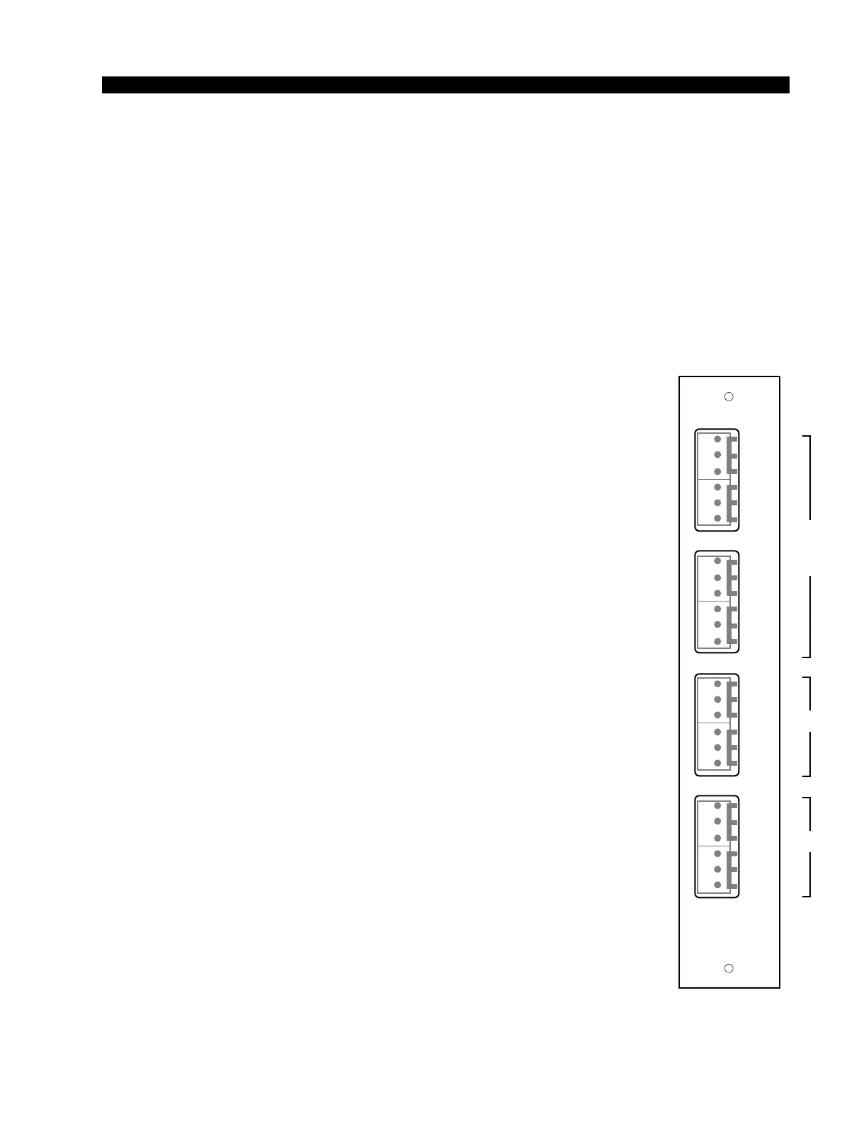
CRD-70/1 Connections — Audio
Includes external stereo inputs and studio outputs. All audio signals are
analog, +4dBu balanced.
Pin 6 – Lt Ext 1 In LO
Pin 5 – Lt Ext 1 In SH
Pin 4 – Lt Ext 1 In HI
Pin 3 – Rt Ext 1 In LO
Pin 2 – Rt Ext 1 In SH
Pin 1 – Rt Ext 1 In HI
Pin 6 – Lt Ext 2 In LO
Pin 5 – Lt Ext 2 In SH
Pin 4 – Lt Ext 2 In HI
Pin 3 – Rt Ext 2 In LO
Pin 2 – Rt Ext 2 In SH
Pin 1 – Rt Ext 2 In HI
*factory default settings
CRD-70/1
Rear Panel
EX1
L
S
H
EX2
LT
RT
L
S
H
L
S
H
L
S
H
LT
RT
CR
L
S
H
ST
LT
RT
L
S
H
L
S
H
L
S
H
LT
RT
MONITOR
1
1
2
3
4
5
6
1
2
3
4
5
6
1
2
3
4
5
6
1
2
3
4
5
6
D-70 / May 2003
SCD-70
CRD-70
CRD-70
and
SCD-70