page 3 – 4
D-70 / Aug 2000
MASTER OUTPUTS
Hook-Ups
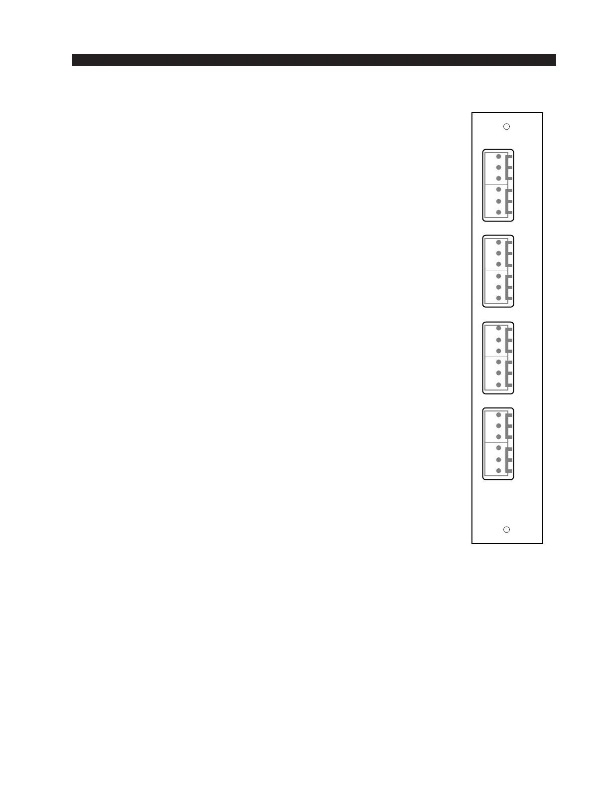
As stated before, all user wiring takes place at six-conductor connec-
tors mounted on the rear panels (OMA-70 and OMD-70).
OMA-70 Connections – Analog Audio Outputs
Includes Program, Audition, Auxiliary 1, and Auxiliary 2 outputs.
All signals are +4dBu balanced.
Pin 6 – PGM Lt Out LO
Pin 5 – PGM Lt Out SH
Pin 4 – PGM Lt Out HI
Pin 3 – PGM Rt Out LO
Pin 2 – PGM Rt Out SH
Pin 1 – PGM Rt Out HI
Pin 6 – AUD Lt Out LO
Pin 5 – AUD Lt Out SH
Pin 4 – AUD Lt Out HI
Pin 3 – AUD Rt Out LO
Pin 2 – AUD Rt Out SH
Pin 1 – AUD Rt Out HI
Pin 6 – AUX1 Lt Out LO
Pin 5 – AUX1 Lt Out SH
Pin 4 – AUX1 Lt Out HI
Pin 3 – AUX1 Rt Out LO
Pin 2 – AUX1 Rt Out SH
Pin 1 – AUX1 Rt Out HI
Pin 6 – AUX2 Lt Out LO
Pin 5 – AUX2 Lt Out SH
Pin 4 – AUX2 Lt Out HI
Pin 3 – AUX2 Rt Out LO
Pin 2 – AUX2 Rt Out SH
Pin 1 – AUX2 Rt Out HI
OMA-70
Rear Panel
ANALOG
OUT
PGM
L
S
H
AUD
LT
RT
L
S
H
L
S
H
L
S
H
LT
RT
L
S
H
LT
RT
L
S
H
L
S
H
L
S
H
LT
RT
1
2
3
4
5
6
1
2
3
4
5
6
1
2
3
4
5
6
1
2
3
4
5
6
AUX
1
AUX
2