page 4 – 4
D-70 / Apr 2000
CONTROL ROOM MODULE
Pin 3 – Rt CR Out LO
Pin 2 – Rt CR Out SH
Pin 1 – Rt CR Out HI
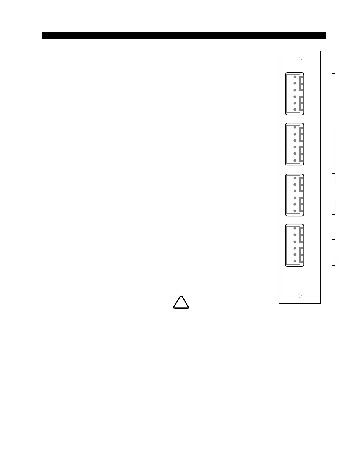
CRD-70/2 Rear Panel Audio Connections:
Includes headphone and cue outputs. All audio signals are +4dBu
balanced, analog stereo.
Pin 6 – Lt HDPN Out LO
Pin 5 – Lt HDPN Out SH
Pin 4 – Lt HDPN Out HI
Pin 3 – Rt HDPN Out LO
Pin 2 – Rt HDPN Out SH
Pin 1 – Rt HDPN Out HI
Pin 6 – Lt Cue Out LO
Pin 5 – Lt Cue Out SH
Pin 4 – Lt Cue Out HI
Pin 3 – Rt Cue Out LO
Pin 2 – Rt Cue Out SH
Pin 1 – Rt Cue Out HI
CRD-70/2 Rear Panel Control Connections:
The console’s on-air tally port is on the CRD-70/2 lower six-conductor
connector. This is a simple relay closure that activates whenever pro-
grammed input modules are turned ON (see page 2-4). The port can be
used to control an externally powered tally light that requires a continuous
closure to function.
Pin 6 – On-Air Tally Relay N.O.
Pin 5 – On-Air Tally Relay COM
!
Maximum current through
the on-air tally relay clo-
sure is 2 amps @30VDC.
CRD-70/2
Rear Panel
HDPN
L
S
H
CUE
RT
L
S
H
L
S
H
L
S
H
RT
OUT
L
S
H
TB
N.
C
AIR
TALLY
TALLY
2
TALLY
3
O.
N.
C
O.
N.
C
O.
MONITOR
2
LT
LT
1
2
3
4
5
6
1
2
3
4
5
6
1
2
3
4
5
6
1
2
3
4
5
6
D-70 / Jan 2001
D-70 / May 2003
SCD-70
CRD-70
SCD-70
CRD-70