page 2 – 7
D-70 / Apr 2000
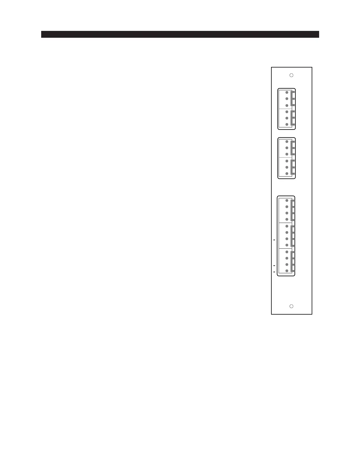
INPUT MODULE
Stereo Line Digital Inputs
Audio Connections
These A and B sample rate converter inputs accept AES-3 or SPDIF
formatted digital audio.
Pin 6 – Line A AES LO
Pin 5 – Line A AES SH
Pin 4 – Line A AES HI
Pin 6 – Line B AES LO
Pin 5 – Line B AES SH
Pin 4 – Line B AES HI
Control Connections
These are identical for stereo line analog and digital versions of the
IND-70 module.
All control ports (except Tally B) are opto-isolated. Functions
include remote on and off, on tally, ready, and start/stop for remote
source machines. Each function is available for the A source port,
allowing it to follow the module's A source selector switch.
Pin 1 – Ready-
Pin 2 – On-
Pin 3 – Ready+
Pin 4 – On+
Pin 5 – Start+
Pin 6 – Off-
Pin 7 – Stop+
Pin 8 – Off+
Pin 9 – Start/Stop Common
Pin 10 – +5V Digital
Pin 11 – B Tally
Pin 12 – Digital Ground
To Turn the Module ON & OFF from a Remote Location
In the case of stereo line input modules, “remote location” can also
refer to a remote source machine that is feeding its audio to the module
in question. A 5VDC signal, as indicated below, will activate the
module’s channel ON and OFF switches.
REMOTE ON — Activates the module’s channel ON switch.
Provide a momentary 5VDC signal between Pins 2 and 4 (On). This
will latch the module ON. Be sure to observe the polarity as indicated
above.
DIG IN
IN A
IN B
DIG
TALLY
C
B
5V
S/S
OFF
STOP
C
OFF
START
ON
RDY
ON
RDY
L
S
H
L
S
H
+
+
+
+
+
+
1
2
3
4
5
6
7
8
9
10
11
12
1
2
3
4
5
6
1
2
3
4
5
6
SRC-70
Rear Panel
D-70 / Sep 2000