page 2 – 8
D-70 / Apr 2000
INPUT MODULE
REMOTE OFF — Activates the module’s channel OFF
switch. Provide a momentary 5VDC signal between Pins 6 and
8 (Off). This will latch the module OFF. Be sure to observe the
polarity as indicated above.
To START and STOP Remote Source Machines Using
Module ON/OFF Switches
EXTERNAL START — Hook up the remote machine’s
“start” control pins to the module’s twelve-conductor connec-
tor control pins: for START wire to pins 5 and 9.
EXTERNAL STOP — Hook up the remote machine’s
“stop” control pins to the module’s twelve-conductor connec-
tor control pins: for STOP A wire to pins 7 and 9.
Note that these are opto isolated outputs. START/STOP
COM (pin 9) connects to the opto emitters, while the remaining
connections (START, pin 5 and STOP, pin 7) connects to the
opto collectors. Correct polarity must be observed in wiring to
these connections.
To Control the Module’s OFF Switch LED with an
External Source Machine
READY — Hook up the remote machine’s “ready” control
pins to the module’s twelve-conductor connector control pins:
for READY wire to pins 1 and 3. The module’s Ready port is
looking for a 5VDC signal with pin 3 positive with respect to
pin 1 (READY). As long as the voltage is present in the correct
polarity, the OFF switch LED will be illuminated.
Tally B
Provides a remote indication that the module’s B source has
been selected. This control function provides a continuous
closure (open collector) between Pin 11 (Tally B) and Digital
Ground (Pin 12) whenever the B source is selected.
This closure can be used to control an externally powered
tally light that requires a continuous closure to function. An
external tally light (i.e., LED) can be powered from the input
module by connecting the external LED to +5V Digital (Pin 10)
and the B Tally ports. In either case, current should not exceed
30 milliamps.
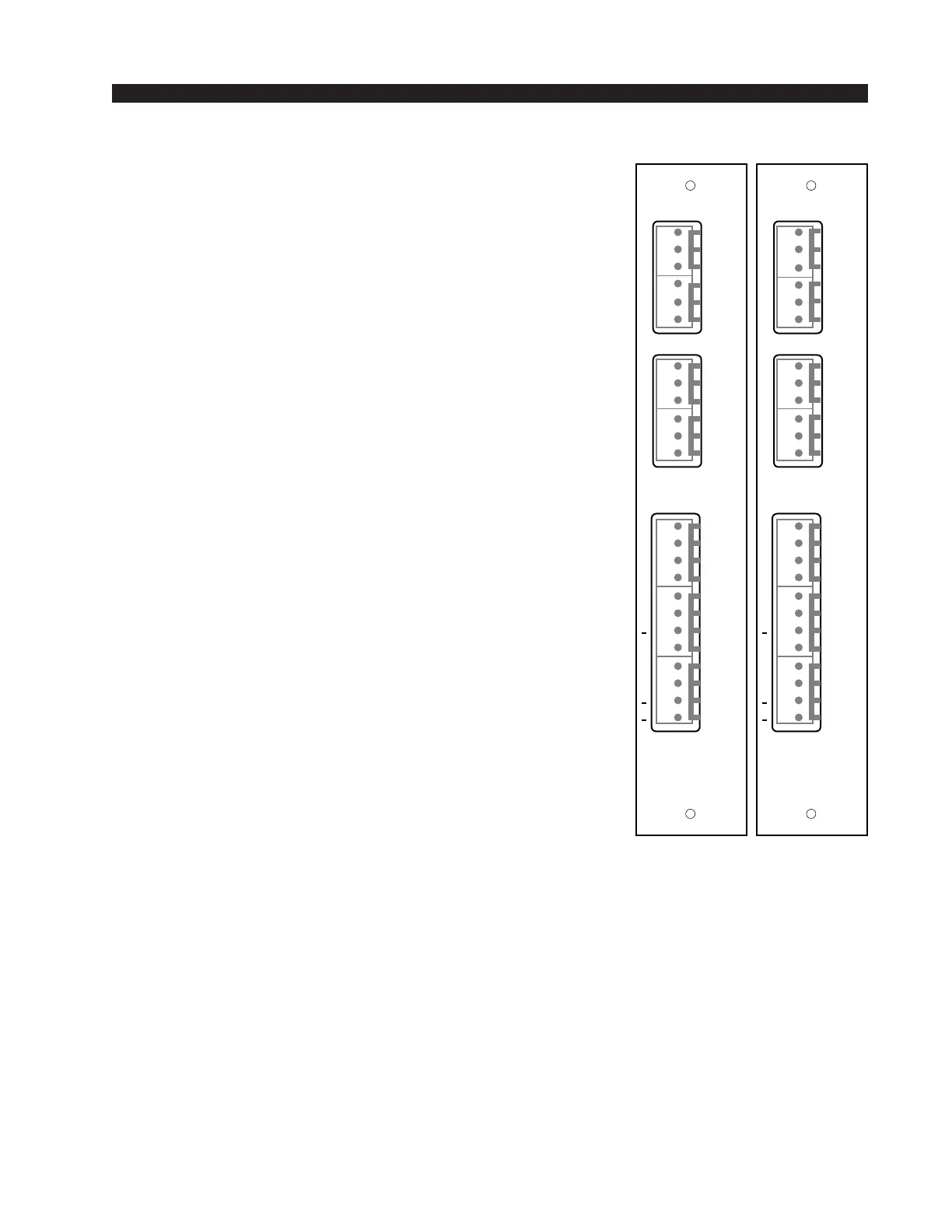
SRC-70
Rear Panel
SLADC-70
Rear Panel
DIG IN
IN A
IN B
DIG
TALLY
C
B
5V
S/S
OFF
STOP
C
OFF
START
ON
RDY
ON
RDY
L
S
H
L
S
H
+
+
+
+
+
+
1
2
3
4
5
6
7
8
9
10
11
12
1
2
3
4
5
6
1
2
3
4
5
6
LINE IN
IN A
L
S
H
IN B
DIG
TALLY
5V
S/S
OFF
STOP
OFF
START
ON
RDY
ON
RDY
LT
RT
L
S
H
L
S
H
L
S
H
LT
RT
C
B
C
+
+
+
+
+
+
1
2
3
4
5
6
7
8
9
10
11
12
1
2
3
4
5
6
1
2
3
4
5
6
We recommend a series
resistor between the LED
and +5V digital when you
are powering the external
tally from the console; a
value of 220Ω (1/4W 5%)
is suggested.