page 2 – 2
D-70 / Apr 2000
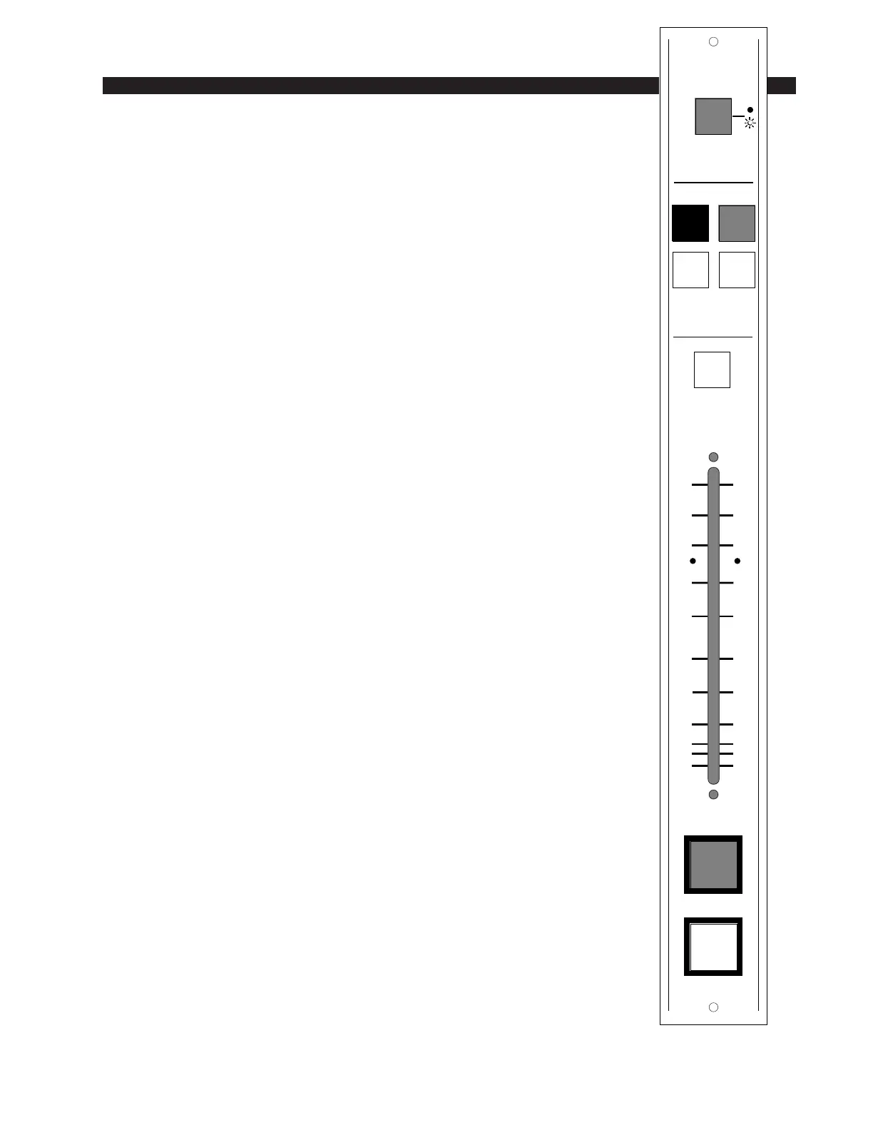
INPUT MODULE
Input Module (IND-70)
Module Overview
The IND-70 is an input module for microphone input signals and for
stereo line input signals. Depending on the type of input signals the
module will handle, it will have an input card for mono microphone
(-50dBu nominal), stereo line analog, or stereo line digital inputs. Each
module accepts two sources, A and B, switched at the top of the module.
The mono version uses an MMADC-70 input card at the input stage
of the module. Phantom power is available at both input ports; it may be
selectively activated by an internal jumper (the factory default is OFF).
PCB-mounted multi-turn trimpots (range 38dB) adjust the level of the
A and B inputs independently.
Example: with a microphone input of –60dBm @150Ω at the port, gain
trim can set levels from -22dBu to +16dBu (note maximum preamp gain is
+76dB).
An insert point (+4dBu balanced) is provided: it is post-trim and may
be internally bypassed, which is the factory default setting.
The ADC (analog-to-digital converter) version uses SLADC-70
input card at the input stage of the module, and accepts +4dBu balanced
analog input signals. PCB-mounted multi-turn trimpots adjust the left
and right levels.
The SRC (sample rate converter) version uses an SRC-70 input card
at the input stage of the module, and accepts digital (AES is factory
default) input signals.
Output switches assign the selected source signal to any combination
of the console’s four stereo outputs: PGM (program), AUD (audition),
AUX1 (auxiliary) and/or AUX2.
Level is set by a long-throw fader.
The channel ON and OFF switches are at the bottom of the module.
In addition to being controlled remotely, these can also be programmed
(via VDIP program) to perform a variety of console control functions,
including activating control room and studio mutes, talkbacks, external
tallies, and timer restart.
All audio and control input and output signals are made via a six-
conductor connector (audio) and a twelve-conductor connector (con-
trol), mounted on the modules’s rear panel.
O
N
O
F
F
0
5
10
15
20
30
40
50
70
00
60
CUE
A
B
PGM AUD
AUX1 AUX2
INPUT
ASSIGN
D-70 / Aug 2000