page 8 – 5
D-70 / Apr 2000
SUPERPHONE INPUT
Hook-Ups
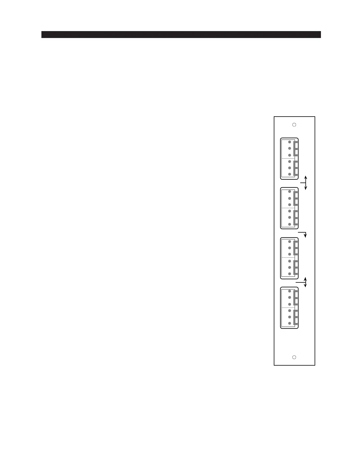
As stated before, all user wiring to and from SPD-70 modules takes
place at six-conductor connectors mounted on the module’s rear panel.
There are four connectors per module: the two upper ones handle audio
input and output signals; the two lower ones audio outputs and control
signals.
Audio Connections (two upper connectors)
These include station Hybrid 1 & 2 inputs and outputs. All are +4dBu
balanced analog mono.
Pin 6 – Hybrid 1 In LO
Pin 5 – Hybrid 1 In SH
Pin 4 – Hybrid 1 In HI
Pin 3 – Hybrid 1 Out LO
Pin 2 – Hybrid 1 Out SH
Pin 1 – Hybrid 1 Out HI
Pin 6 – Hybrid 2 In LO
Pin 5 – Hybrid 2 In SH
Pin 4 – Hybrid 2 In HI
Pin 3 – Hybrid 2 Out LO
Pin 2 – Hybrid 2 Out SH
Pin 1 – Hybrid 2 Out HI
Audio and Control Connections (two lower connectors)
These include module output composite feeds (for recording) and
remote tape machine START/STOP ports.
Pin 6 – Callers Only Out LO
Pin 5 – Callers Only Out SH
Pin 4 – Callers Only Out HI
Pin 3 – Composite Minus Callers Out LO
Pin 2 – Composite Minus Callers Out SH
Pin 1 – Composite Minus Callers Out HI
Pin 6 – Composite Out LO
Pin 5 – Composite Out SH
Pin 4 – Composite Out HI
Pin 3 – Start
Pin 2 – Start/Stop Common
Pin 1 – Stop
When the module’s ON/START switch is pressed, a closure takes
place between start/stop common and START; when the module’s OFF
switch is pressed, a closure takes place between start/stop common and
STOP. These may be used to control a remote tape machine for recording
phone segments. These are opto isolated outputs. The Start/Stop Common
connects to the opto emitters, while Stop and Start connect to the opto
collectors. Observe correct polarity when using these outputs.
SPD-70
Rear Panel
L
S
H
IN
OUT
L
S
H
L
S
H
L
S
H
L
S
H
C
L
S
H
L
S
H
CALLER
IN
OUT
1
1
2
2
A
L
L
M
I
C
S
C
O
M
P
START
COM
STOP
MIX
MIX
CALLER
1
2
3
4
5
6
1
2
3
4
5
6
1
2
3
4
5
6
1
2
3
4
5
6