page 7 – 9
D-70 / Apr 2000
V I R T U A L D I P S W I T C H
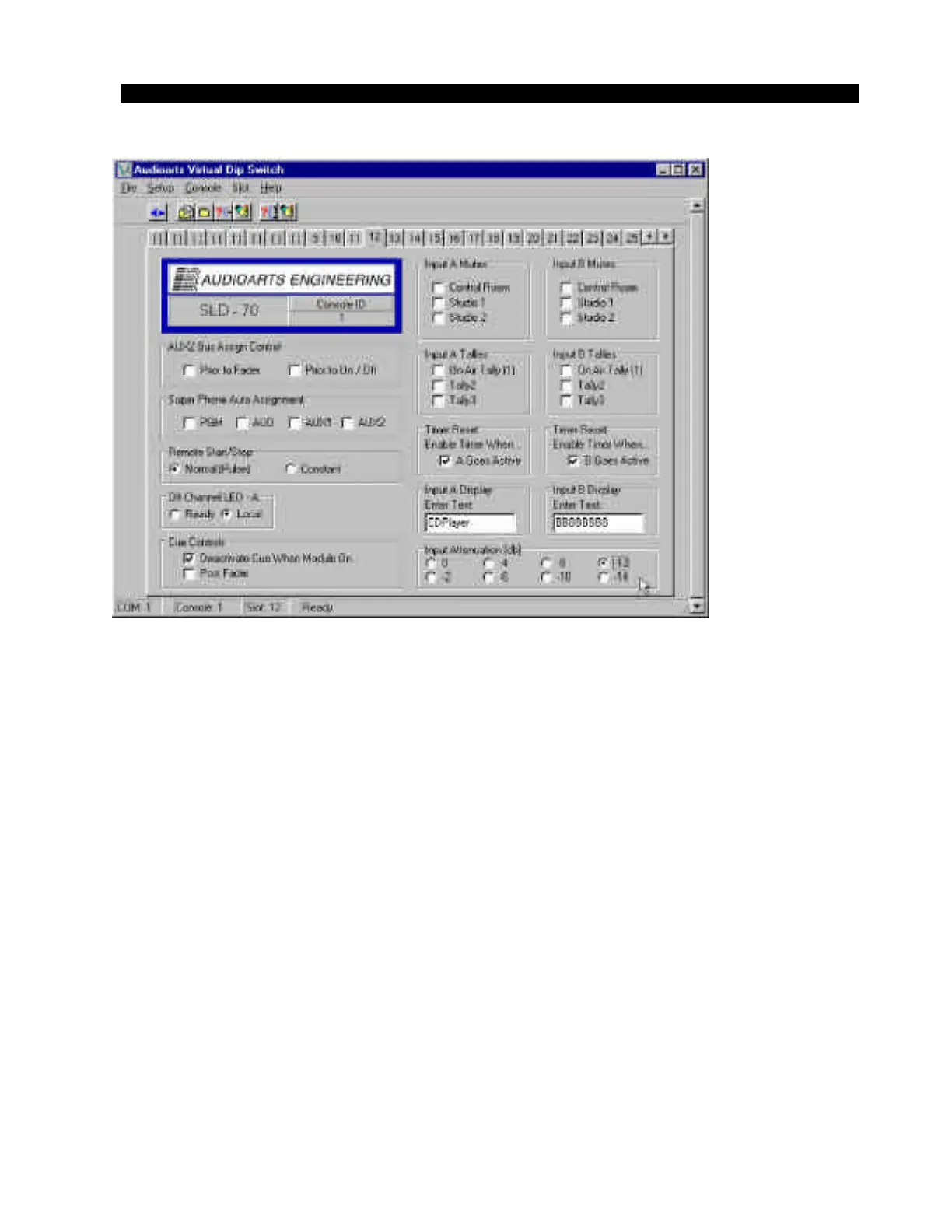
In the lower right corner of the VDip screen (figure 8) there are eight
mutually exclusive radio buttons for selecting the desired input attenu-
ation. The attenuation choices are 0db to -14dB in 2 dB steps. Simply
click on the appropriate radio button to select the attenuation value and
then “WRITE” the selected change to the module. You can use the
“Write Slot” toolbar icon or the “Slot” menu item to write the current
attenuation setting along with any other module settings. The attenu-
ation setting is immediately written to the corresponding channel.
Why use digital attenuation?
Many of today’s digital audio sources (especially modern rock, rap,
etc.) are produced to take full advantage of the available maximum
digital output level (0dBFS). Playback of these tracks from a CD
player’s digital output result in average digital domain levels -6 to
-3dBFS or higher! That translates to average analog levels of +18 to
+21 dBu; very close to the console’s clipping point of +24dBu.
Connecting the digital output from a CD player to a console input with
gain on the fader can put the operator in a position of potentially
clipping the CD playback. In this case, adding -12dB of attenuation will
re-calibrate the input module so that digital clipping of CD source
material will be impossible even if the operator pushes the fader all the
way to the top.
Figure 8
D-70 / May 2001