12. Setting of the DUO limit switching (option)
Any application can be switched on or off via the two intermediate position
switches.
For setting, the switching point (intermediate position) must
be approached from the same direction as afterwards in
electrical operation.
12.1 Setting for direction CLOSE (black section)
.
Move valve to desired intermediate position.
.
Press down and turn setting spindle G (figure K-2) with screw driver
(5 mm) in direction of arrow, thereby observe pointer H.
While a ratchet is felt and heard, the pointer H moves 90° every time.
When pointer H is 90° from mark C, continue turning slowly. When pointer
H has reached the mark C, stop turning and release setting spindle. If you
override the tripping point inadvertently (ratchet is heard after the pointer
has snapped), continue turning the setting spindle in the same direction
and repeat setting process.
12.2 Setting for direction OPEN (white section)
.
Move valve to desired intermediate position.
.
Press down and turn setting spindle K (figure K-2) with screw driver
(5 mm) in direction of arrow, thereby observe pointer L.
While a ratchet is felt and heard, the pointer L moves 90° every time.
When pointer L is 90° from mark F, continue turning slowly. When pointer
L has reached the mark F, stop turning and release setting spindle. If you
override the tripping point inadvertently (ratchet is heard after the pointer
has snapped), continue turning the setting spindle in the same direction
and repeat setting process.
15
Multi-turn actuators SA 07.1 – SA 16.1
Operation instructions with actuator controls AMB 01.1/AMB 02.1
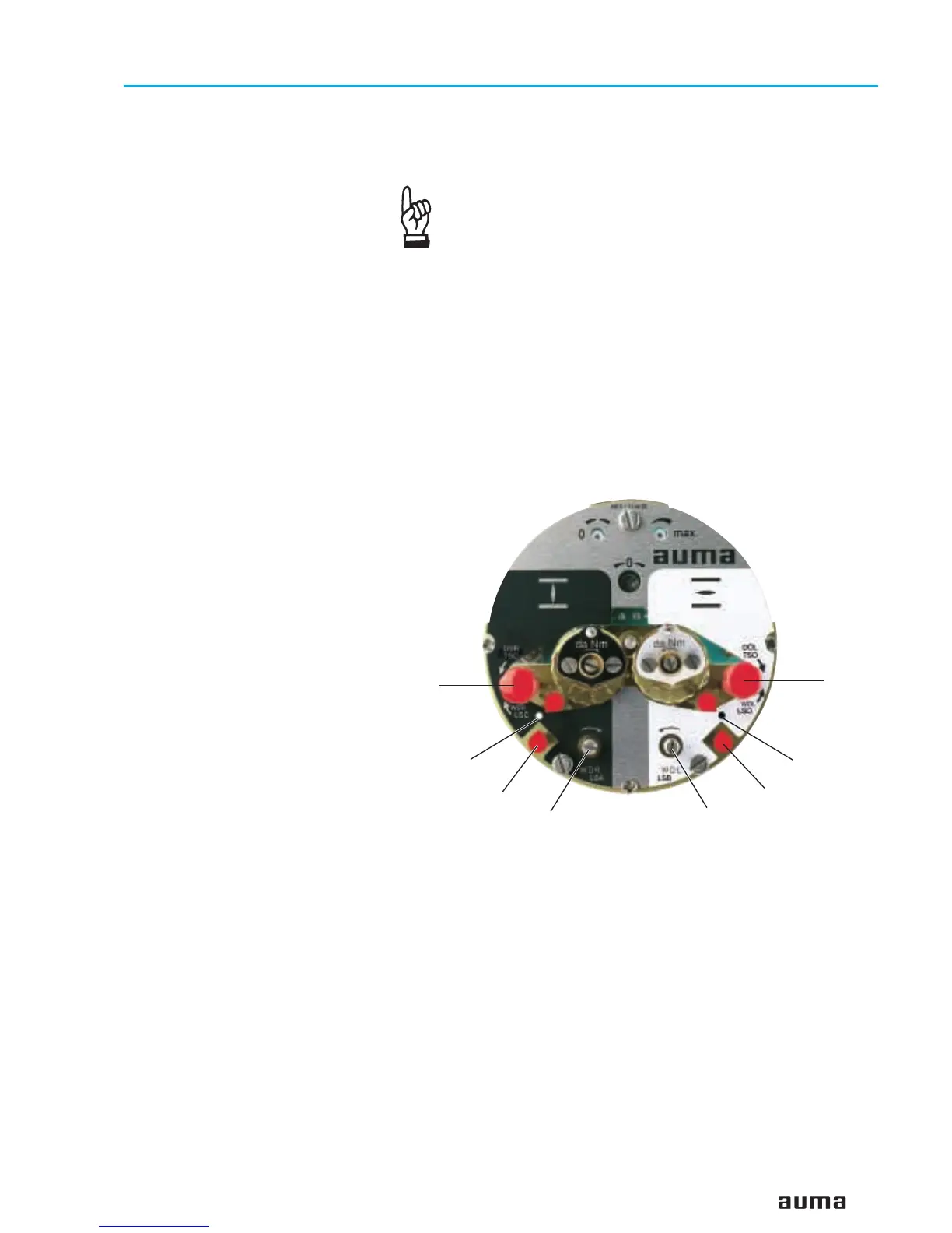
Figure K-2: Control unit
G
T
H
C
K
P
E
F

 Loading...


