19.6 Settings on relay board for potential-free feedback (option)
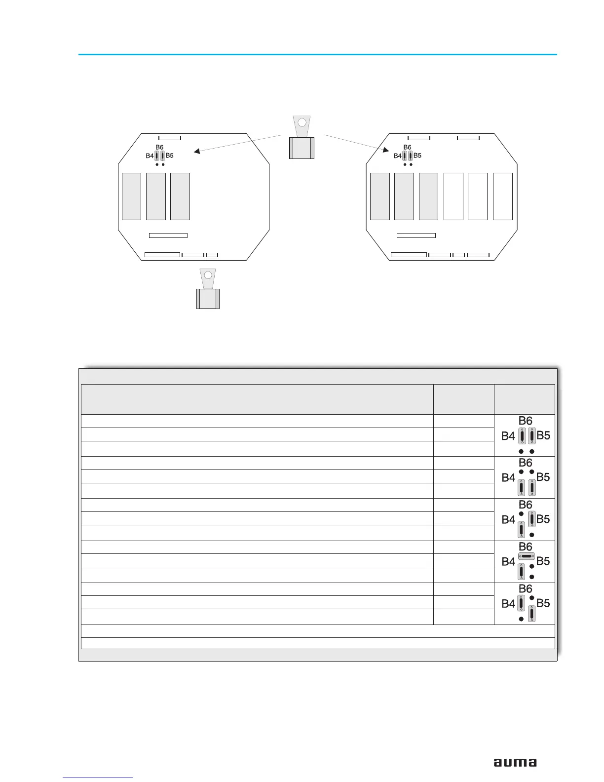
Only valid for versions (B02 and B04) with relays K6, K7, K8 on relay board.
.
Remove cover (figure R-1, page 23) of AUMA MATIC BASIC.
.
Assign the required functions to the terminals XK ... of the customer
connection (see wiring diagram) with the red plug-in links, according to
table 8.
.
Clean sealing faces of housing and cover
.
Check whether O-ring is in good condition.
.
Apply a thin film of non-acidic grease to the sealing faces.
.
Replace cover and fasten bolts evenly crosswise.
25
Multi-turn actuators SA 07.1 – SA 16.1
Operation instructions with actuator controls AMB 01.1/AMB 02.1
K6 K7K8 K6 K7K8
Figure T1: Relay board version B02 Figure T2: Relay board version B04
Plug-in links
Function
(Signal on terminal XK ...
1)
active, if the function is correct)
Signal
available on
terminal
1)
Link
Torque switch tripped in mid-travel and/ or thermoswitch or thermal overload relay tripped XK 16
No torque switch tripped in mid-travel XK 15
No thermoswitch or no thermal overload relay tripped XK 13
No torque switch tripped in mid-travel XK 15
Torque switch tripped in mid-travel XK 16
No function XK 13
No torque switch tripped in mid-travel XK 15
Torque switch tripped in mid-travel XK 16
No thermoswitch or no thermal overload relay tripped XK 13
No torque switch tripped in mid-travel XK 15
Torque switch tripped in mid-travel XK 16
Thermoswitch or thermal overload relay tripped XK 13
Torque switch tripped in mid-travel XK 16
No torque switch tripped in mid-travel XK 15
No function XK 13
Common link to XK 14
1) refer to order-related wiring diagram BSP … KMS TP ...
Table 8

 Loading...


