14. Test run
14.1 Check direction of rotation This check is only required for multi-turn actuators with 3-ph AC motor.
.
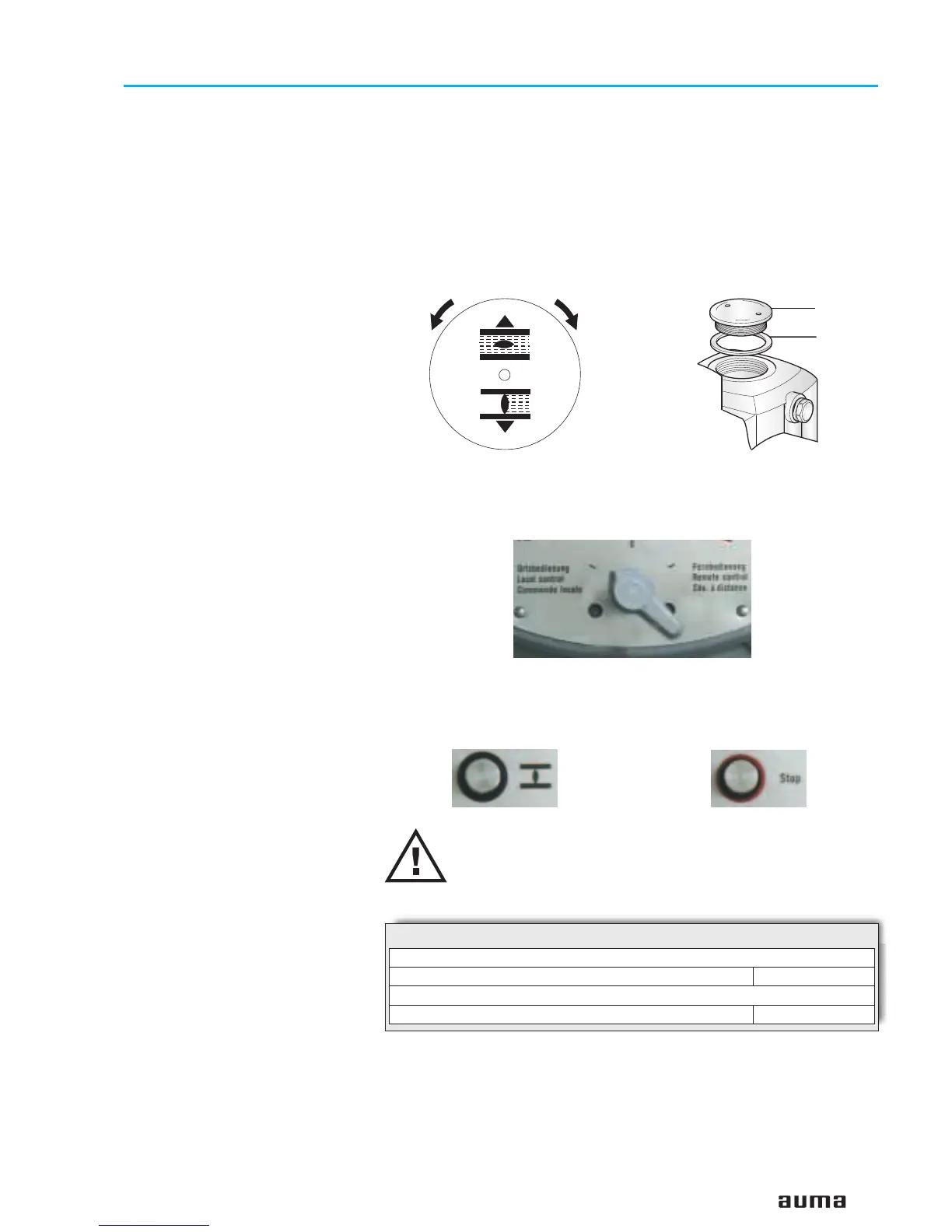
If provided, place indicator disc on shaft.
The direction of rotation of the indicator disc (figure M-1) indicates the
direction of rotation of the output drive.
.
If there is no indicator disc, the direction of rotation can also be observed
on the hollow shaft. To this end, remove screw plug (no. 27) (figure M-2).
.
Move actuator manually to intermediate position or to sufficient distance
from end position.
.
Set selector switch to local control (I)(figure M-3).
.
Switch on the voltage supply.
.
Operate push-button CLOSE (figure M-4) and observe the direction of
rotation:
If the direction of rotation is wrong switch off immediately
with push-button “Stop” (figure M-5) or by turning both test
buttons T and P (figure K-2) simultaneously in any direction.
Correct phase sequence at motor connection. Repeat test run.
17
Multi-turn actuators SA 07.1 – SA 16.1
Operation instructions with actuator controls AMB 01.1/AMB 02.1
Figure M-1: Indicator disc
CLOSE OPEN
Figure M-2: Opening the hollow shaft
27
S1/S2
Figure M-3: Selector switch on local controls
Figure M-5: Push-button STOPFigure M-4 Push-button CLOSE
Direction of rotation of the indicator disc:
counterclockwise correct
Direction of rotation of the hollow shaft:
clockwise correct
Table 6:
 Loading...