7. Mounting to valve/ gearbox
.
Prior to mounting the actuator must be checked for
damage. Damaged parts must be replaced by original
spare parts.
.
After mounting to valve/ gearbox, touch up any possible
damage to paint finish.
Mounting is most easily done with the valve shaft/gearbox shaft pointing
vertically upward. But mounting can be done in any other position as well.
The multi-turn actuator leaves the factory in position CLOSED (limit switch
CLOSED tripped).
.
Check if mounting flange fits the valve/ gearbox.
Spigot at flanges should be loose fit!
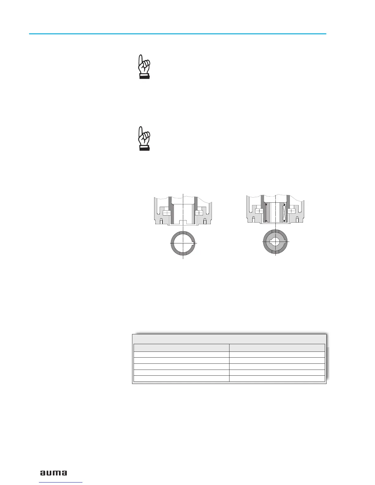
The output drive types B1, B2, B3 or B4 (figure A) are delivered with bore
and keyway (usually according to ISO 5210).
For output drive type A (figure B-1), the internal thread of the stem nut must
match the thread of the valve stem. If not ordered explicitly with thread, the
stem nut is unbored or with pilot bore when delivered. For finish machining
of stem nut refer to next page.
.
Check whether bore and keyway match the input shaft of valve/gearbox.
.
Thoroughly degrease mounting faces at multi-turn actuator and valve/
gearbox.
.
Apply a small quantity of grease to input shaft of valve/gearbox.
.
Place actuator on valve/ gearbox and fasten. Fasten bolts (at least
quality 8.8, refer to table 3) evenly crosswise.
8
Multi-turn actuators SA 07.1 – SA 16.1
with actuator controls AMB 01.1/AMB 02.1 Operation instructions
Figure A
Output drive type B1/B2
Plug sleeve
Output drive type B3/B4
Bore with keyway
Strength class 8.8 T
A
(Nm)
M 8
25
M 10
50
M 12
87
M 16
220
M 20
420
Table 3: Fastening torque for bolts

 Loading...


