16. Setting of electronic position transmitter RWG (option)
– For remote indication or external control –
After mounting the multi-turn actuator to the valve, check setting by
measuring the output current (see subclause 16.1 or 16.2) and re-adjust, if
necessary.
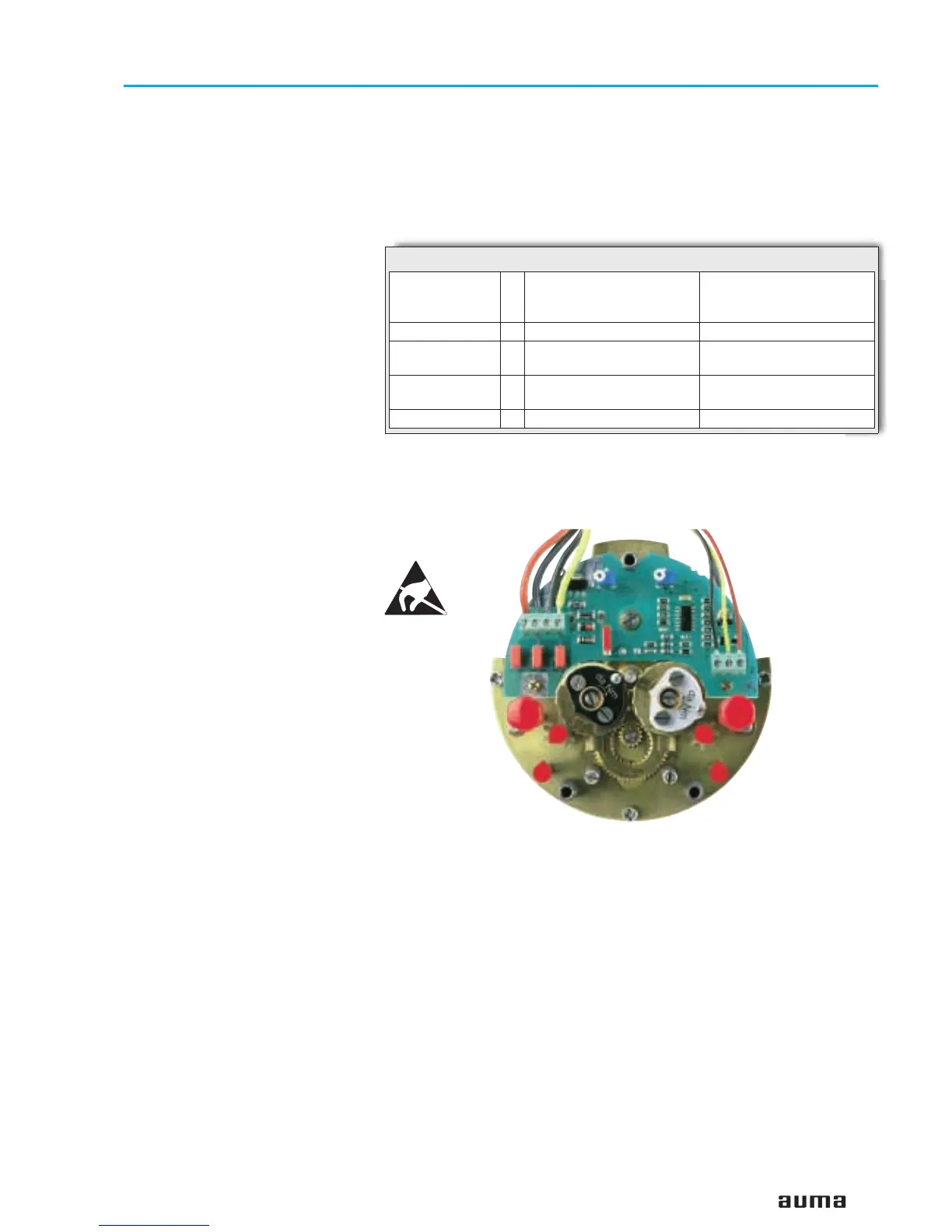
The position transmitter board (figure P-1) is located under the cover plate
(figure P-2).
19
Multi-turn actuators SA 07.1 – SA 16.1
Operation instructions with actuator controls AMB 01.1/AMB 02.1
Wiring diagrams BSP. . . KMS TP_ _ 4 / _ _ _
3-/ 4-wire system
BSP. . . KMS TP _ 4 _ / _ _ _
BSP. . . KMS TP _ 5 _ / _ _ _
2-wire system
Output current I
a
0 – 20 mA, 4 – 20 mA 4 – 20 mA
Power
supply
U
v
24 V DC, ± 15 %
smoothed
14 V DC + (I x R
B
),
max. 30 V
Max.
current input
I 24 mA at 20 mA
output current
20 mA
Max. load R
B
600 Ω (Uv - 14 V) / 20 mA
Table 7: Technical data RWG 4020
Figure P-1: Position transmitter board

 Loading...


