13. Setting of the torque switching
13.1 Setting
.
The set torque must suit the valve!
.
This setting should only be changed with the consent of
the valve manufacturer!
.
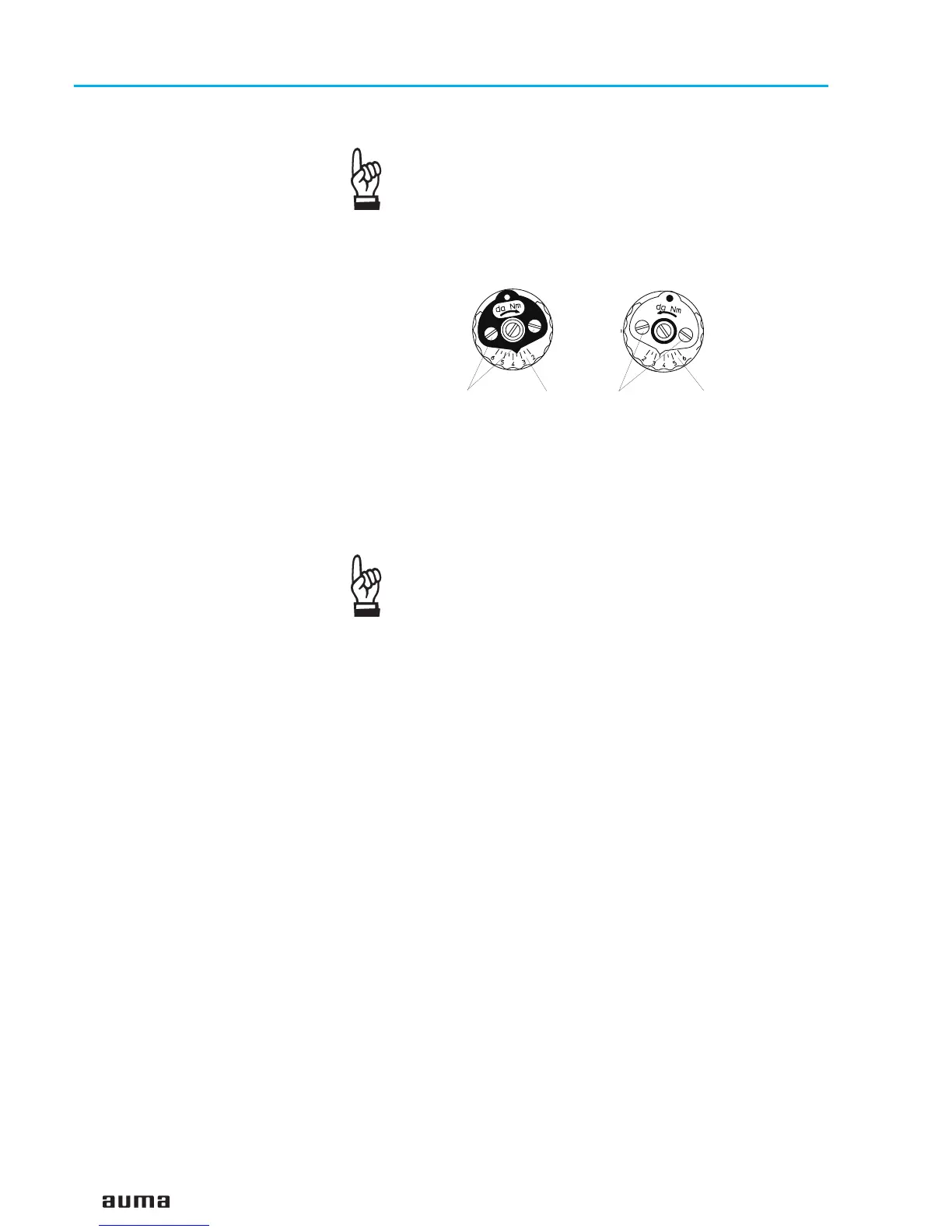
Loosen both lock screws O at the torque dial (figure L).
.
Turn torque dial P to set it to the required torque (1 da Nm = 10 Nm).
Example:
Figure J shows the following setting:
3.5 da Nm = 35 Nm for direction CLOSE
4.5 da Nm = 45 Nm for direction OPEN
.
Tighten lock screws O again
.
The torque switches can also be operated in manual
operation.
.
The torque switching acts as overload protection over full
travel, also when stopping in the end positions by limit
switching.
13.2 Checking the switches for torque and DUO limit switching
The red test b
uttons T and P (figure K-2) serve for operating the torque
switches manually:
.
Turning T in direction of the arrow TSC (DSR) triggers torque
switch CLOSED.
.
Turning P in direction of the arrow TSO (DÖL) triggers torque
switch OPEN.
.
If a DUO limit switching (optional) is installed in the actuator, the
intermediate position switches will be operated at the same time.
16
Multi-turn actuators SA 07.1 – SA 16.1
with actuator controls AMB 01.1/AMB 02.1 Operation instructions

 Loading...


