10
Axess Pro Series 3000 Owner Installation Instructions
NOTE: 5 metres of
communication cable is
supplied with the opener.
WARNING! Do not turn the power on
to the opener before connecting either
console.
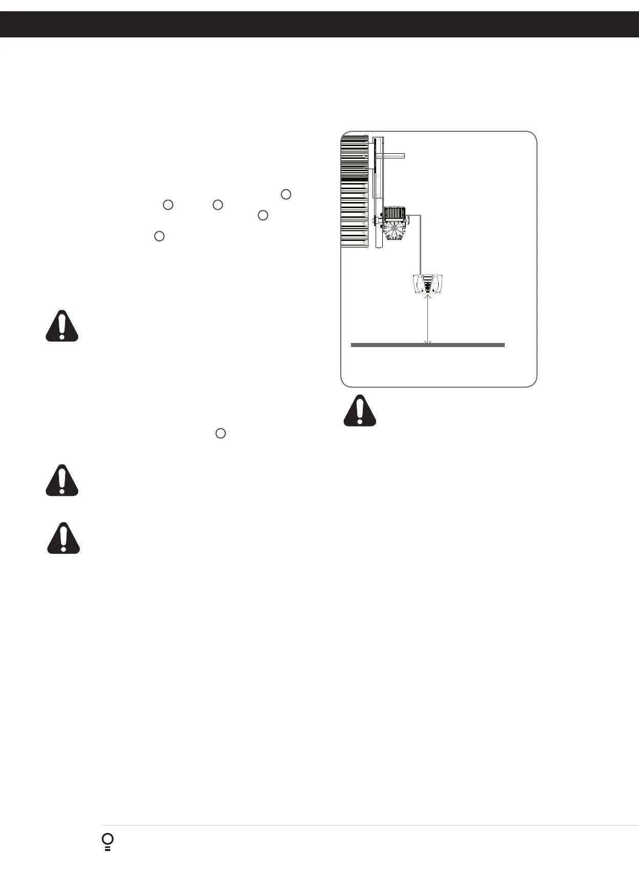
Floor
1.5 metre from floor
7.1 Mounting The Drive Unit
Open the shutter about one metre from the floor.
Raise the drive unit to the required height by using a suitable lifter
or use chain block connected to a secure beam above the shutter
axle.
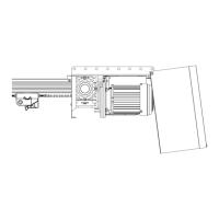
a. Position opener and secure with four M12x35 screws
10
.
b. Mount drive sprocket
6
on shaft
5
in line with shutter drive
gear. Tighten the grub screw on the sprocket
6
with M4 hex
key.
c. Shorten drive chain
7
as required and fit around drive gears.
d. Feed manual chain (not supplied) through guide and over the
clutch pulley.
e. Shorten the manual chain as required and fix ends to make a
loop.
NOTE: Ensure that hand chain is not twisted when making a loop.
WARNING! Do not turn the power on to the opener
before connecting either console.
7.2 Installing The Logic Or Manual Console
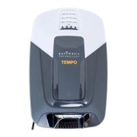
1. Remove the main cover.
2. Affix the logic or manual console at a height of 1.5 metres
within sight of the shutter. Make sure that the position of
the logic or manual console is out of reach of children and
convenient to the customer (Fig. 7.1).
3. Connect the communication cable
2
from the opener to the
logic or manual console unit.
WARNING! For full automatic operation a Photo Electric
Beam Sensor (Safety Beam) must be fitted with logic
console. Failure to comply will void the warranty and may
cause serious personal injury and/or property damage.
WARNING! Ensure that network cable is affixed properly
and away from the moving parts of the shutter and
opener.
7. Installation
Fig 7.1


 To Next Page