Owner Installation Instructions Axess Pro Series 3000 13
9. Safety Beam Installation
Fig 6.3
WARNING: When using Safety Beams, the doorway must be
clear of all obstructions and persons at all times. The location
of the beams and manner in which it is installed might not
give safety protection at all times. Check to make sure
that the height of the beam and type used give maximum
protection possible
WARNING: Tampering with Safety Beams could result in
serious personal injury and/or property damage and will void
the warranty.
V+
IN3
V−
RED
BLUE
GREEN
GOLD
BLACK
BLACK
BLACK
BLACK
YELLOW
RED
YELLOW
RED
+
+
-
-
RED
P.E BEAM
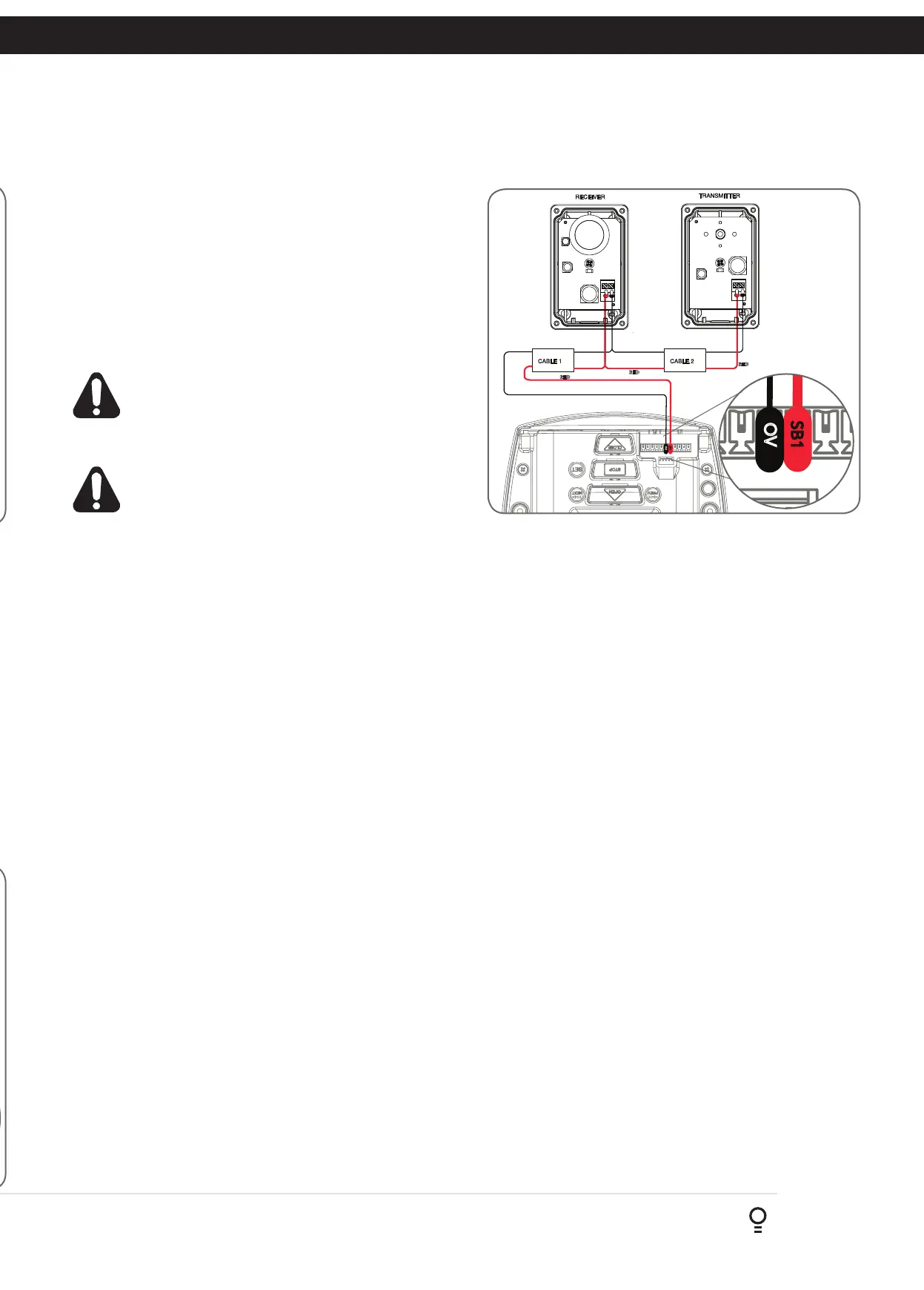
9.3 Wiring the Safety Beam to V2 Logic Console
a. Connect the wires from the Safety Beams wiring harness to
terminal block.
i. By default the Axess
®
Pro Series 3000 will only take two wire
safety beams (connect one wire to SB3, SB2 or SB1 input and
the second wire to 0V, next to the SB1 terminal (Fig. 9.4) ).
ii. The V2 Console can take up to three (3) two wire safety beams
but is NOT compatible with three wire safety beams.
b. Make sure to align the beams correctly. Follow the manual supplied
with the Safety Beams.
WARNING: When using Safety Beams, the doorway must be
clear of all obstructions and persons at all times. The location
of the beams and manner in which it is installed might not
give safety protection at all times. Check to make sure
that the height of the beam and type used give maximum
protection possible
WARNING: Tampering with Safety Beams could result in
serious personal injury and/or property damage and will void
the warranty.
9.4 Alignment
a. Power up the Axess
®
Pro Series 3000 with the Safety Beam
connected. The green LED on the transmitter should turn ON to
indicate power is present.
b. If the receiver is connected to power and the red LED is flashing
while the green LED on the transmitter is on, the transmitter and
receiver are not aligned.
c. Make horizontal and/or vertical adjustment on the transmitter and/
or receiver until the red LED on the receiver turns on, indicating
alignment. Approaching to the alignment is indicated by fast
flashes on the red receiver LED.
SB1
OV
RED
BLACK
RED
BLACK
RED
BLACK
BLACK
Fig 9.4
SB1
OV
RED
BLACK
RED
BLACK
RED
BLACK
BLACK