Owner Installation Instructions Axess Pro Series 3000 9
6. Pre-Installation Requirements
The Axess
®
Pro Series 3000 is designed to operate most
industrial heavy duty roller shutters. The shutter must be in good
working condition and travel freely in the guides.
6.1 Initial Check
Before commencing installation, check the following:
a. The shutter moves freely for the full travel in both directions.
b. The mounting must be a solid construction (concrete, brick
or steel) and must be able to withstand the full driving force
applied to the shutter.
c. For full automatic operation a Safety Beam must be fitted to
the logic console. The Safety Beam should be positioned as
close to the shutter as practicable.
SINGLE PHASE (3105 & 3110 models): Require a 240V 10 Amp
power point located within one metre of the drive unit.
6.2 Selecting the installation location
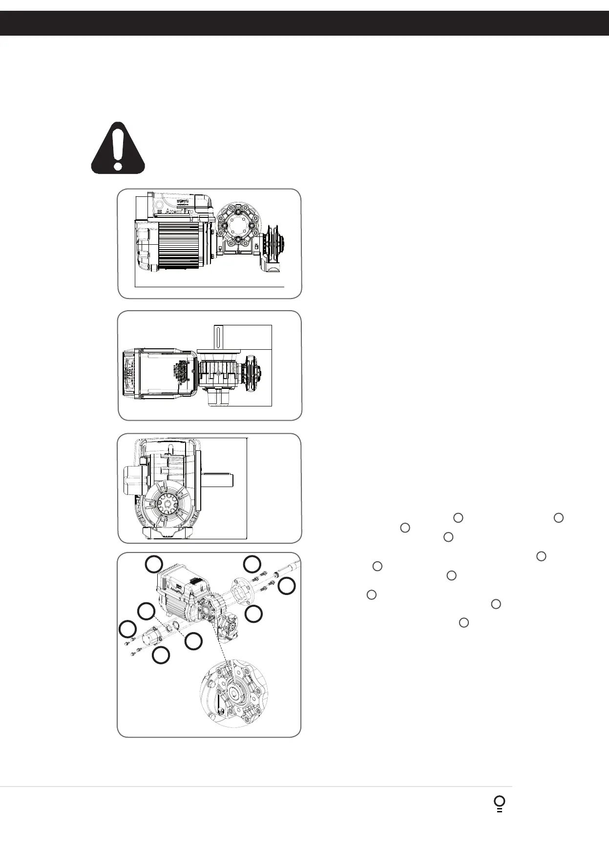
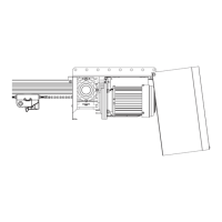
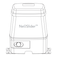
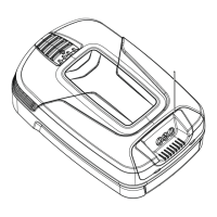
Overall dimensions of the opener are shown in Fig. 6.1 - 6.3.
When selecting the installation location, consider the following:
• Minimum distance between the shutter drum and mounting
plate needs to be more than 15mm and less than 100mm.
• Minimum distance between the drive unit and the imposing
structure is 10mm.
• The overhead clearance needs to be at least 150mm.
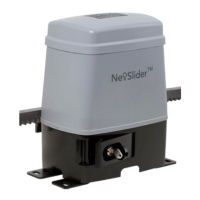
6.3 Drive Unit Pre-assembly
The opener can be installed on either the right- or left hand side
of the shutter (when viewed from inside the building). The timing
assembly, mounting flange and drive shaft needs to be assembled
according to the installation side. Assembling the opener for RIGHT-
HAND installation is listed below and shown in Fig 6.4. For LEFT-
HAND side installation, assemble the parts from the other end.
a. Assemble the mounting flange
4
with four M8x38 screws
9
to the drive unit
1
.
b. Insert the output drive shaft
5
into the gearbox, thread side
first.
c. Secure the output drive shaft with the lock washer
11
and
lock nut
12
.
d. Finger tighten the lock nut*
12
then lock it by securing the
position of the lock nut by bending one tooth of the lock
washer
11
into the slot on the lock nut. (Fig 6.4 insert)
e. Line up the shaft of the timing assembly
3
with the keyway
on the back of the drive shaft. Push and secure the timing
assembly with four M8x20 bolts
8
ensuring the cable gland
is facing the motor.
NOTE: The drive unit is not designed to be mounted upside
down. Gearbox damage will result.
* Finger tighten the lock nut, this will remove any movement
in the output shaft. Excessive tightening to lock nut may cause
damage to output shaft bearing.
495mm
85mm
200mm
260mm
IMPORTANT SAFETY INSTRUCTIONS FOR INSTALLATION
Warning: Incorrect installation can lead to severe injury.
Follow ALL installation instructions.
Fig 6.1
Fig 6.2
Fig 6.3
Fig 6.4
9
5
4
1
8
3
10
11