Chapter 6: Accessories
Page 6–17Stellar
®
SR55 Series Soft Starter User Manual – 1st Ed, Rev F – 09/18/2019
replaCemenT/spare parTs (ConTinued)
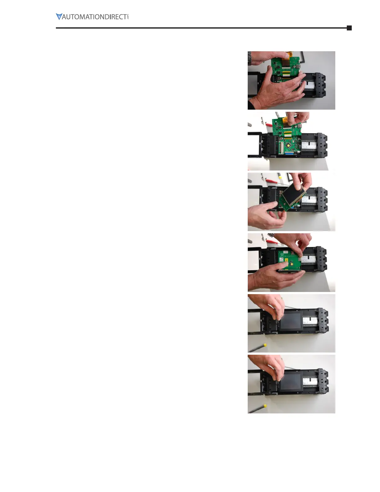
TouChsCreen replaCemenT/insTallaTion insTruCTions (ConTinued)
5) On the reverse side of the PCB, remove the FFC
cable from the socket (lift gray part from front
edge; do not force.)
6) Place the replacement screen FFC cable in
socket, making sure that it is correctly seated.
Push the gray part down to lock.
7) Once the socket is locked with the FFC cable
firmly connected, gently place the board back in
to the previous position, using the same angled
technique.
8) Place the PCB flat in position.
9) Make sure that the screen is correctly aligned,
and place the outer bevel back on the LCD
display.
10) Once you have placed the outer bevel back
on the LCD display, ensure that the two plastic
rivets below the LCD display are re-installed.

 Loading...