Appendix B: Soft Starter Application Considerations
Page B–9Stellar
®
SR55 Series Soft Starter User Manual – 1st Ed, Rev F – 09/18/2019
b.3.2 – The induCTion moTor (ConTinued0
figure b.3.2.1: Torque/speed Curve – induCTion moTor
K
TORQUE
Full Load Torque ( FLT, M
A
Pull-up Torque
Synchronous speed
Torque/Speed Curve – Induction Motor
Locked Rotor
Torque
( LRT, M
A
)
0 SPEED S
figure b.3.2.2: Torque/speed Curve – Coupled load
Each load coupled to an induction motor has its own speed/torque curve:
K
TORQUE
Pull-up Torque
Full Load Torque ( FLT, M
N
Synchronous speed
0 SPEED S
Torque/Speed Curve – Coupled Load
Locked Rotor
Torque
( LRT, M
A
)
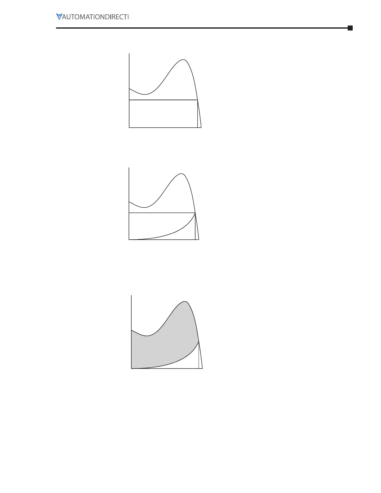
figure b.3.2.3: Torque/speed Curve – aCCeleraTing Torque
The acceleration of a motor-load system is caused by the difference between the developed
torque (motor) and the absorbed torque (load), and is shown by the shaded area in the next
figure:
0 SPEED S
Torque
( LRT, M
A
)
K
Pull-up Torque
Full Load Torque ( FLT, M
N
Synchronous speed
Torque/Speed Curve – Accelerating Torque
TORQUE

 Loading...