Chapter 2: Electrical Installation
Page 2–3Stellar
®
SR55 Series Soft Starter User Manual – 1st Ed, Rev F – 09/18/2019
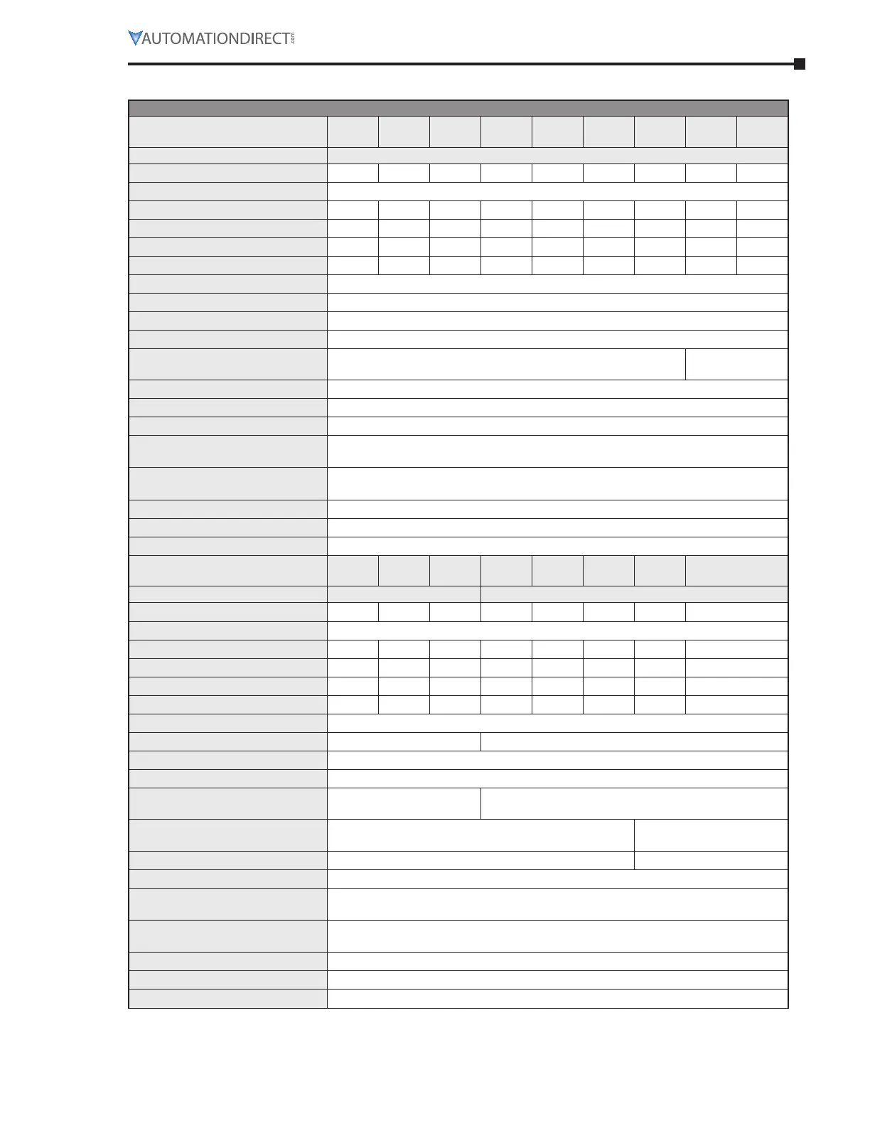
elecTRIcAl specIfIcATIoNs
ELECTRICAL SPECIFICATIONS – SR55 Series Full-Featured Soft Starters
Model
SR55
-017
SR55
-021
SR55
-027
SR55
-034
SR55
-040
SR55
-052
SR55
-065
SR55
-077
SR55
-096
Frame Size 1
Rated Current [UL FLC] (A)
17 21 27 34 40 52 65 77 96
Rated Operational Voltage
200VAC to 480VAC
Motor Rating @ 200V (hp)
3 5 7.5 10 10 15 20 20 30
Motor Rating @ 208V (hp)
5 5 7.5 10 10 15 20 25 30
Motor Rating @ 230V (hp)
5 5 7.5 10 10 15 20 25 30
Motor Rating @ 460V (hp)
10 15 20 25 30 40 50 60 75
Trip Class
programmable 10 to 30
Index Rating [per IEC 60947-4-2]
I
e
: AC-53a: 3.5–17: 90–5
Impulse Withstand Voltage
4kV
Insulation Voltage Rating
480V
Short-Circuit Current Rating
(type 1)
5kA 10kA
Control Power Consumption
60W inrush to latch internal bypass relays; 4W steady state
Control Voltage Range
24VDC +10%-15% or 110–230 VAC +10%-15%
Control Fuse (external)
4A
Control Inputs
(3) DI @ 24VDC, 110VAC, or 230 VAC; (1) PTC Thermistor;
(1) AI @ 0–10VDC 10mA max or 4–20mA
Control Outputs
(3) N/O relay and (1) N/C relay @ 30VDC 0.5A / 230VAC 1A resistive;
(1) AO @ 0–10VDC 10mA max or 4–20mA
Start Time Setting Range
1 to 300 seconds
Start Voltage Setting Range
10% to 100%
Stop Time Setting Range
0 to 300 seconds
Model
SR55
-124
SR55
-156
SR55
-180
SR55
-242
SR55
-302
SR55
-361
SR55
-414
SR55-477
Frame Size 2 3
Rated Current [UL FLC] (A)
124 156 180 242 302 361 414 477
Rated Operational Voltage
200VAC to 480VAC
Motor Rating @ 200V (hp)
40 50 60 75 100 125 150 150
Motor Rating @ 208V (hp)
40 50 60 75 100 125 150 150
Motor Rating @ 230V (hp)
40 60 60 75 100 150 150 150
Motor Rating @ 460V (hp)
100 125 150 200 250 300 350 400
Trip Class
programmable 10 to 30
Index Rating [per IEC 60947-4-2]
I
e
: AC-53a: 3.5–17: 90–5 I
e
: AC-53a: 3.5–17: 90–3
Impulse Withstand Voltage
4kV
Insulation Voltage Rating
480V
Short-Circuit Current Rating
(type 1)
10kA 18kA
Control Power Consumption
60W inrush to latch internal bypass relays; 4W steady state
120W inrush;
4W steady state
Control Voltage Range
24VDC +10%-15% or 110–230 VAC +10%-15% 110VAC +10%-15%
Control Fuse (external)
4A
Control Inputs
(3) DI @ 24VDC, 110VAC, or 230 VAC; (1) PTC Thermistor;
(1) AI @ 0–10VDC 10mA max or 4–20mA
Control Outputs
(3) N/O relay and (1) N/C relay @ 30VDC 0.5A / 230VAC 1A resistive;
(1) AO @ 0–10VDC 10mA max or 4–20mA
Start Time Setting Range
1 to 300 seconds
Start Voltage Setting Range
10% to 100%
Stop Time Setting Range
0 to 300 seconds

 Loading...