5.Installationandinitialoperation
24
©CopyrightReservedAutonicsCo.,Ltd.
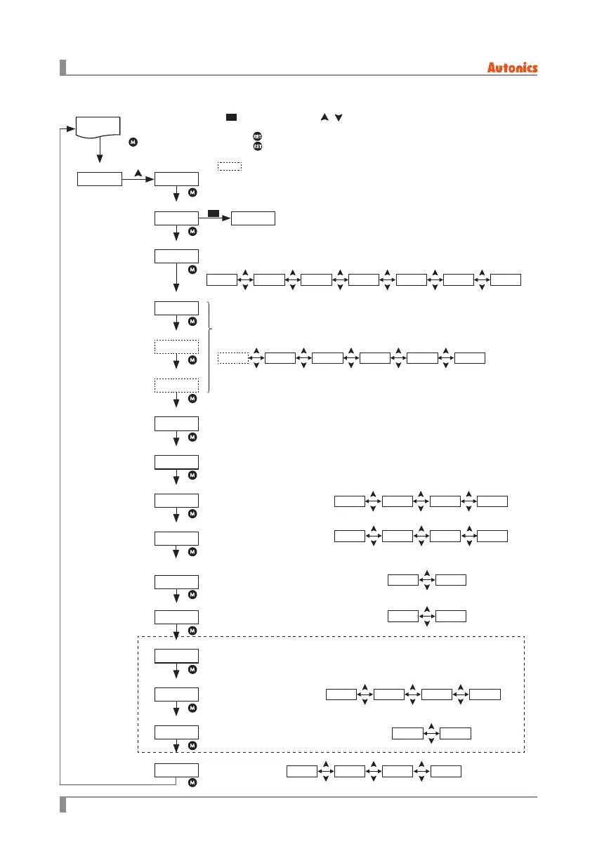
5.3.4 SettingMode1[
ST-1
]
Displays setting mode 1.
Select input type.
Select control method.
Select digital input.
※
Multi SP function [ SP-M] is available only in DI-1.
Set input correction value.
• Set range : -99.9 to 99.9%
Set input slope correction value.
• Set range : -99.9 to 99.9%
Select display value content.
Select bar graph display content.
Select display method of load resistance value.
Select full load auto recognition enable/disable.
Set communication address.
• Set range : 1 to 99
Select communication speed
(baud rate).
Select lock function.
Select communication write enable/disable.
(ENA: Enables to write, DISA: Disables to write)
OP
ST-1
DRES
4-20IN-P
P
F-LD
C-MD
ADDR
DI-1
BAUD
DI-2
COMW
DI-3
LOCK
IN-B
SPAN
DISP
BAR
Operating Mode Setting Mode 1
Control input type
Control method
DI-1 function
DI-3 function
DI-2 function
Input correction
Input slope correction
Display value content
Bar content
Load resistance
display method
Full load auto recognition
Com. address
Com. speed
Com. write
Lock
ONOFㅉV-CYF-CYW-FBㅉC-FBV-FBPA
HOLD
RSTSP-3SP-2SP-1SP-M
REFKWAMPLD-V
REFKWAV
3841929648
LOC3LOC2LOC1OFF
UPDOWN
ONOFF
DISAENA
※
Displayed only for RS485 communication option model.
※
1
RUN
mode
Press key
for 3 sec.
※
1.
P
: Press any key among , .
※
If there is no operation any keys in 30sec., it returns to RUN mode.
※
Press the
key when entering ST-1 setting mode in any parameters, it moves to ST-1.
Press the
key once more, it returns to RUN mode.
※
When setting [ LOCK] as LOC2 or LOC3, and entering ST-1, it displays only [ LOCK] parameter.
※
: This parameter may or may not appear, depending on the other parameter settings.