6.Parametersettingandfunctions
35
©CopyrightReservedAutonicsCo.,Ltd.
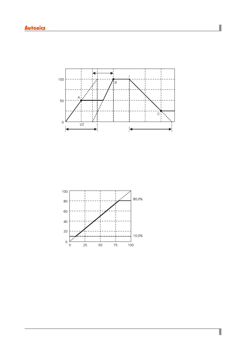
6.2.7 Slowup/Slowdown
It is same purpose as soft start function.
Soft start starts only one time at rst but slow up/slow down function start during operation.
Regardless of control method setting (phase control or cycle control), it operates as phase control.
A : Soft start ends, B : Slow up ends, C : Slow down ends
When it reaches to the target output value, slow up/slow down functions end. When it sets as ‘0’,
slow up/slow down do not operate.
• Set range: 0 to 100 (unit: sec.)
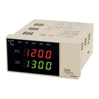
6.2.8 Outputhighlimitvalue[
H-OL
],Outputlowlimitvalue[
L-OL
]
This function is to high/low limit output range to protect load.
• Set range: 0 < output low limit value < output high limit value < 100 (unit: %)
Output(%)
SOFT START set time
Time
SLOW UP set time
SLOW DOWN set time
Output high-limit: H-OL
Output low-limit : L-OL
Control input signal(%)
Output(%)