IP Office Installation
Installation Manual Page 82
IP Office 2.1 40DHB0002USCL Issue 10c (11th May 2004)
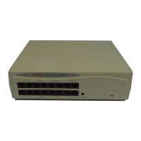
External Control Port (3.5mm Stereo Jack Socket)
Pin No. Description
1 Circuit 1.
2 Circuit 2.
3 0 Volts (Ground/Chassis)
4 Not connected.
5 Not connected.
Control Circuit Information
Control Circuit 1 Pin 2 and Pin 3, ensure that Pin 2 is at a positive voltage with respect to Pin 3.
Control Circuit 2 Pin 1 and Pin 3, ensure that Pin 1 is at a positive voltage with respect to Pin 3.
Each circuit can be switched independently.
Switch Setting Information
ON Low resistance between Pins.
OFF High resistance between Pins.