105
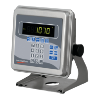
Model E1070 Indicator Service Manual
SensorComm Hardware Configuration and Calibration
SensorComm will only connect to communications port #1
Com Port #1 RS232, RS485 or SensorComm
GND TX / TXA RTS/TXB RX / RCA CTS/RCB +15VDC
BLK RED GRN YLW BLU WHT
Main PCB jumper settings need to be set for RS485. This requires disas-
sembly of the indicator and moving the jumper on JMP1 to pins 2 and 3. See
the next section on Disassembly and Reassembly.
Wiring connections, at the indicator, are shown in the table above.
Refer to SensorComm installation manual for SensorComm box wiring.
1. Access the Service (0701) menu. . .
CAL is displayed.
2. Press the UNITS key. . .
SCALE is displayed.
3. Press the PRINT key. . .
SOURCE is displayed.
4. Press the PRINT key. . .
ANALOG or S-COM is displayed.
5. Press the UNITS key to display S-COM.
6. Press the ENTER key. . .
SensorComm is now enabled.
7. Press the ESC key to exit and ENTER to save the configuration at the
prompt.
Enable SensorComm
Only one SensorComm box
can be connected to the
indicator. The indicator can be
1000 feet from the Sensor-
Comm box.