114
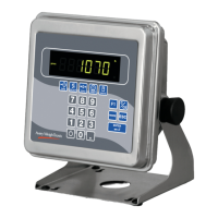
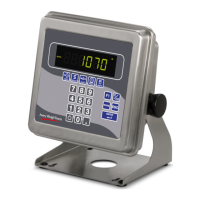
Model E1070 Indicator Service Manual
X=Not applicable
UBx = Under Target Bars
TGx = The word target has multiple LED’s under it. The x represents which LED to turn on.
Opx = Represents the outputs
N,et = Net LED’s
T,are = Tare LED’s
Obx = Over Target Bars
CMx = Comma’s
Annunciator map
As you can see the annunciator “NET” is broken into two different bits. One
for “N”, the other for “ET”. The host indicator will transmit a “1” or true in
both bit positions to activate the annunciator “NET”. It is acceptable to
trigger off the first letter to turn on the whole annunciator, if the other prod-
ucts are not designed in the same manner.
Example:
Transmit 20000 lb of Gross weight with Gross.
A typical serial string is as follows:
Mode 1&2 and RD4100 mode Serial String:
G<SP>20000<SP>lb<CR>
Example:
Transmit 20000 lb of Gross weight with Gross, Motion, and all Under
bar(UB1-6) segments turned on.
A typical serial string is as follows:
Mode 3&4 Serial String:
G<SP>20000<SP>lb<CR><AN1><AN2><AN3><AN4><AN5><AN6><AN7><AN8><CR><LF>
<AN1> = 0x7E
<AN2> = 0x38
<AN3> = 0x00
<AN4> = 0x00
<AN5> = 0x01
<AN6> = 0x00
<AN7> = 0x00
<AN8> = 0x00
If communications is lost between the host and the slave, the slave will
display “-“, middle dashes until a signal is acquired again. The timeout for
this error to occur should be 5-10 seconds in duration.
Annunciator Byte Bit 7 Bit 6 Bit 5 Bit 4 Bit 3 Bit 2 Bit 1 Bit 0
AN1 TG0 XXXXXXCM1
AN2 ET N ROSS G ~ ->0<- TG1 CM2
AN3 OP3 OP2 OP1 RINT P ARE T CM3
AN4 Peak/Count PT X Cust X X X CM4
AN5 X X X X X KG LB CM5
AN6 X XXXXXXCM6
AN7 X UB1 UB2 UB3 UB4 UB5 UB6 X
AN8 X OB1 OB2 OB3 OB4 OB5 OB6 X
Communications
Timeout:
 Loading...