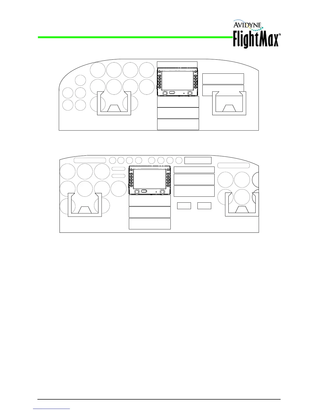
Figure 2: Sample EX500/EX600 Panel Placements
Installation Manual
Cooling Requirements P/N 600-00175-000 Rev 04
- 14 -
4.4 Cooling Requirements
The EX500/EX600 includes internal cooling provisions to maximize operational reliability.
➥ Make sure that the air vents located at the rear and sides of the unit/tray assembly are not
obstructed.
4.5 Positioning and Mounting the EX500/EX600 Tray
The unique requirements of your aircraft will determine the specifics of the installation, as shown in
Figure 2. However, make sure that you install the EX500/EX600 with the following clearances:
● Leave four inches (4”) of clearance behind the tray to allow for connector clearance and permit air
circulation through the EX500/EX600.
● Leave a minimum of 1/8” clearance between the tray and other avionics for air circulation
purposes.
● The Avidyne mounting trays provide for a 0.125" clearance between the bezel and mounting tray
(along the sides and top of the tray) to allow for any panel thickness.
AUDIO PANEL
GPS/NAV/COM
GPS/NAV/COM
AUTOPILOT
ADF OR OTHER
AVIONICS
TRANSPONDER
AUDIO PANEL
GPS/NAV/COM
GPS/NAV/COM
AUTOPILOT OR OTHER
AVIONICS
TRANSPONDER
ADF OR OTHER AVIONICS
MFD PLACEMENT IN PANEL OF
LARGER AIRCRAFT (TYPICAL)
MFD PLACEMENT IN PANEL OF
SMALLER AIRCRAFT (TYPICAL)
EX600 or
EX500
EX600 or
EX500