16 ME-02 USER MANUAL MD004
_____________________________________________________________________________________________
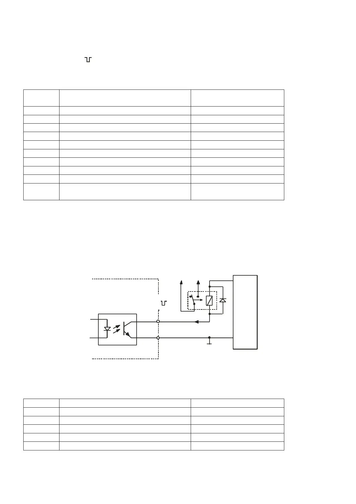
5.2 Transoptors output
P1-P8 outputs of WY are used to connect 8 batching devices or 6 batching devices and START/STOP,
ZERO signals.
Placement description - marker no. and wires colors:
GND
(external gnd, transoptors emiters)
Transoptor outputs are open collector type with load 50mA / 24V. Directly relays or relays board offered by AXIS
can be connected to the outputs. AXIS also offers steering box (supply, 3 or 8 relays). We suggest to use
dedicated relays boards MS 8K/P (8 relays type RM96P – load 3A/250V) or complete steering box.
Attention: Relays coils must be secured by eg. 1N4148 diode.
Direct connection between relay and steering output (WY):
1P1
+24V
0V
0GND
Supply
Relay
Iwy
WY
Scale
Steering signals START/STOP and ZERO are available on additional connector WY+. Moreover safety threshold
is added (read special function FUNC/ProtECt):
* colors might change
 Loading...