Installation
It's possible to enable clockwise (CW) and counter-clockwise
(CCW) motor rotation by connecting the +LM SW and -LM
SW inputs.
They may be used to block motor rotation when the machines
overflow contact is intercepted.
Note - When one of these said contacts is intercepted
the motor stops with the required inertia.
The Enable input in regards to this input always has priority.
To enable such a function, you must:
-- Open soldering point S10
-- Open soldering point S12 ( disable a internal allarm for
missing tachogenerator or encoder).
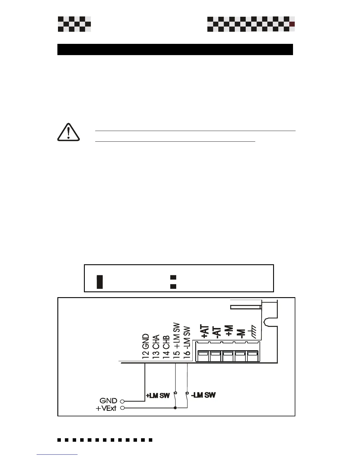
-- Then connect on said input a positive voltage (between
+5Vdc and + 24Vdc) coming from -for example two N.C.
contacts. You may connect an external supply "combining
negative" as well as from one of the supplies furnished on the
Microspeed Plus. Function: At opening one of the following
contacts you enable the motor rotation in the corresponding
direction.
3.10 Limit Switch Input +/-
=NOT ENABLE =+/- LIMIT SW. ENABLE