63
Service Manual
Plus
MICROSPEED
Option
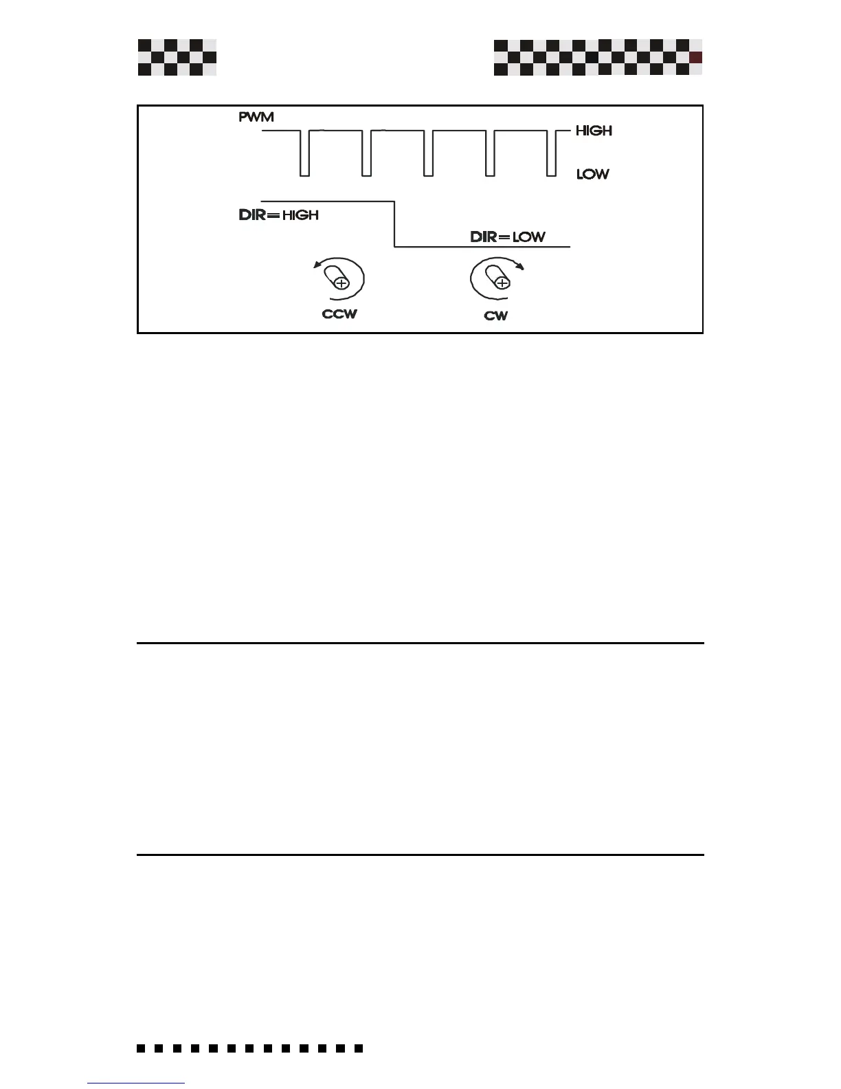
--With High PWM logic signal and any DIR logic value you have
zero output voltage between +M and -M. (Motor output
terminal).
--With logic signa PWM = H and DIR = L you receive
clockwise motor rotation.
--With logic signal PWM = H and DIR = H you receive counter-
clockwise motor rotation.
NOTE:
--The motor wiring must be connected correctly. (Consult the
connections diagram furnished with the motor).
For additional information contact AXOR.
Signal Connector Description.
1 Drive OK, Open Collector output 50mA Max. (Normally
closed, opens when in protection mode).
3 and12 GND Common zero signal
4 Auxiliary output voltage +10V, 4mA.
5 Auxiliary output voltage -10V, 4mA.
6 Enable (+10/30 Volt drive enabled)
7 PWM input Frequency
8 DIR input Direction
Note: -The other pins connector are N.C
-For the leds indicator, in this option,see Chapter 2.2
-The only active adjustemente in this option are RIN and
RIP.
-If closed S16 or S17 you insert for PWM and DIR input a
pull-up resistor of 3.3 Kohm to internal +14V.