Do you have a question about the Axor Microspeed Plus Series and is the answer not in the manual?
Explains safety symbols (Danger, Warning), and general directives for safe installation and operation.
Introduces the Microspeed Plus Servo Amplifier, its capabilities, feedback types, and operating parameters.
Details available speed feedback methods and optional features like current reference and limit switches.
Provides detailed technical specifications including voltage, current ratings, PWM frequency, temperature, and weight.
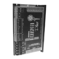
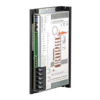
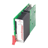
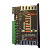
Identifies and describes the physical components and connection terminals of the Microspeed Plus drive.
Presents mechanical dimensions and diagrams for the Microspeed Plus servo amplifier.
Explains how to interpret the product label, including the ordering code and identification of options.
Illustrates the terminal layout and connectivity for the Microspeed Plus drive.
Details the function of signal connector pins 1 (OK) and 2 (TPRC), including current limit modes.
Continues the description of signal pins 3-10, covering GND, voltage outputs, enable, and reference inputs.
Describes signal inputs 11-14 for encoder feedback and input 15 for limit switch functions.
Outlines the power supply connections for the drive, including positive, negative, motor, and ground terminals.
Explains the purpose and adjustment of ACC, VEL, BIL, and KV potentiometers for drive control.
Details the DER potentiometer and notes on KV/DER adjustments using a hexadecimal switch.
Describes reversible and irreversible protection mechanisms and common fault conditions.
Explains the status indicated by the drive's OK, IN, ST, OC, and MD LEDs.
Provides essential guidelines for physically mounting and positioning the Microspeed Plus drive.
Covers ventilation requirements and recommendations based on drive model and operating conditions.
Details the design and rating considerations for power supplies, transformers, and protection components.
Provides formulas for calculating secondary voltage (V1) based on motor voltage and speed requirements.
Discusses transformer power calculation, capacitor filters, and voltage ratings for filters.
Explains the role of discharge resistors and provides formulas for calculating their value and wattage.
Covers fuse selection for primary and secondary circuits of the transformer, with calculation formulas.
Demonstrates correct wiring techniques for connecting multiple Microspeed Plus drives in parallel to a single supply.
Illustrates proper grounding and shielding practices for signal and power cables to minimize interference.
Provides further guidelines on ground cable length, shielding, and motor power cable connections.
Outlines EMC standards and assembly criteria, including network filters, shielded cables, and grounding.
Discusses EMC filter selection criteria and calculation methods for filter dimensions.
Presents electrical characteristics of recommended EMC filters, including leakage current and power loss.
Lists specific EMC filters, their dimensions, and crucial notes for proper installation and connection.
Shows a practical wiring example using a CNC for differential reference and enabling the drive.
Demonstrates speed reference connections using common mode and an internal power supply with a speed potentiometer.
Explains how to command the drive in torque mode using voltage output and calculate current based on TPRC input.
Describes limiting output current using a positive voltage range, keeping the speed loop active.
Details limiting output current with a resistance load at TPRC, specifying values for 50% current limitation.
Explains enabling directional motor rotation blockage using +LM SW and -LM SW limit switch inputs.
Recommends power cable specifications and addresses motor inductance requirements for connection.
Lists pre-startup checks, drive characteristics, and guides the user on how to proceed with setup.
Provides sequential steps for powering up the drive, setting reference signals, and verifying system operation.
Guides on accessing internal settings, adjustment pads, and solder bridges for drive personalization.
Explains the function of key adjustment components like RDT, RA, RIN, RIP, RKV, GAIN, RAMP, RENC.
Continues the description of adjustment components, focusing on CKV and CDER capacitors for velocity loop tuning.
Describes the functions of solder bridges S1-S7, crucial for configuring drive behavior and features.
Continues the description of solder bridges S8-S17, covering encoder feedback, PWM/DIR inputs, and pull-up resistors.
Details speed adjustment using tachogenerator feedback and the calculation of the RDT resistor for setting speed.
Explains using armature feedback for speed control and the calculation of the RA resistor for voltage constant adaptation.
Covers the RCA resistor calculation for compensating motor internal resistance and the BIL potentiometer for zero speed offset.
Describes the use of the BIL potentiometer to adjust motor to zero speed.
Provides tables for selecting RIN and RIP resistors to set nominal and peak motor current limits.
Explains how to adjust acceleration and deceleration ramp times using potentiometers and resistors.
Guides on adjusting proportional (KV) and derivative (DER) gains for high inertia loads.
Illustrates waveform adjustments for KV and DER gains and mentions the CDER capacitor for derivative constant.
Lists common problems, diagnostic indicators (LEDs), and solutions for drive malfunctions.
Details the encoder feedback option, including its benefits, technical specs, and solder bridge configurations.
Shows typical wiring diagrams for connecting encoders to the drive and motor.
Illustrates how to connect an external power supply to the drive for encoder signal power.
Explains setting up speed control with encoder feedback, including RENC resistor calculation.
Describes using PWM and Direction signals for motor speed and direction control via a controller.
Illustrates PWM/DIR signal logic, their effect on motor rotation, and notes on connections and adjustments.