Chapter 7. LIST OF SIMPLE CONFIGURATION DISPLAY ITEMS
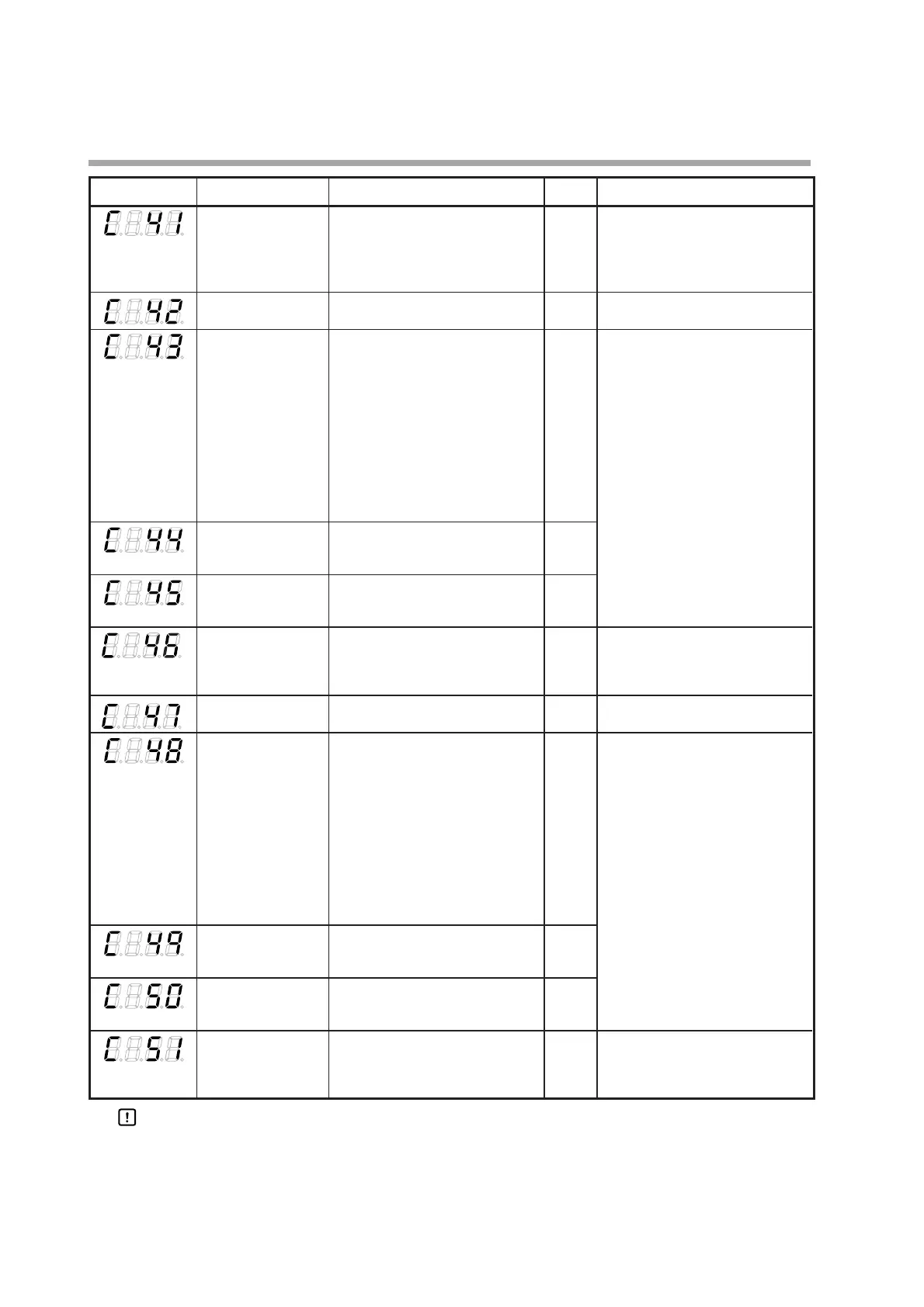
Display Item Contents
Initial value
Notes
CT2 measurement 30 to 300 ms. 30 Displayed when the optional model
wait time has two current transformer input
points and the CT2 operation type is
set at "heater burnout detection"
(C39=0).
Output 1 range 1: 4 to 20 mA 1 Displayed when the control output 1
2: 0 to 20 mA of the model is the current output.
Output 1 type 0: MV 0 Displayed when the control output 1
1: Heat MV (for heat/cool control) of the model is the current output.
2: Cool MV (for heat/cool control) The decimal point position of the
3: PV output 1 low limit/high limit becomes
4: PV value before bias 1 digit after the decimal point when
5: SP the output 1 type is related to the MV
6: Deviation and CT. When the output 1 type is
7: CT1 current value related to the PV, SP, and deviation,
8: CT2 current value the decimal point position becomes
9: MFB (invalid on SDC15) the same as that of the PV.
10: SP+MV
11: PV+MV
Output 1 scaling -1999 to +9999 0.0
low limit (The decimal point position may vary
depending on the output 1 type.)
Output 1 scaling -1999 to +9999 100.0
high limit (The decimal point position may vary
depending on the output 1 type.)
Control output 1 MV 0 to 9999 200 If the controller model uses current
scaling The decimal point position and unit output for control output 1 and if the
are same as for PV. control output 1 type is SP+MV or
PV+MV, this setting is displayed.
Output 2 range 1: 4 to 20 mA 1 Displayed when the control output 2
2: 0 to 20 mA of the model is the current output.
Output 2 type 0: MV 3 Displayed when the control output 2
1: Heat MV (for heat/cool control) of the model is the current output.
2: Cool MV (for heat/cool control) The decimal point position of the
3: PV output 2 input range low limit/high
4: PV value before bias limit becomes 1 digit after the decimal
5: SP point when the output 2 type is related
6: Deviation to the MV and CT. When the output 2
7: CT1 current value type is related to the PV, SP, and
8: CT2 current value deviation, the decimal point position
9: MFB (invalid on SDC15) becomes the same as that of the PV.
10: SP+MV
11: PV+MV
Output 2 scaling -1999 to +9999 0
low limit (The decimal point position may vary
depending on the output 2 type.)
Output 2 scaling -1999 to +9999 1000
high limit (The decimal point position may vary
depending on the output 2 type.)
Control output 2 MV 0 to 9999 200 If the controller model uses current
scaling The decimal point position and unit output for control output 2 and if the
are same as for PV. control output 2 type is SP+MV or
PV+MV, this setting is displayed.
Handling Precautions
• If ROM version 1 of the instrument information bank(Id02) is prior to
2.04, SP+MV and PV+MV cannot be set in [Control output 1 type],
[Control output 2 type], and [Auxiliary output type ].
• If ROM version 1 of the instrument information bank(Id02) is prior to
2.04, SP+MV and PV+MV cannot be set in [Control output 1 MV scaling],
[Control output 2 MV scaling], and [Auxiliary output MV scaling ].
7-6