4-2
■ Terminal assignment label symbols
The following table shows the meanings of the symbols used for the terminal
assignment label attached to the side panel of this unit.
■ Wiring Precautions
• Before starting the wiring work, carefully check the label on the side panel of this
unit to understand the model No. and terminal No. to carry out the wiring
properly.
• For panel mount type(C15T), use an appropriate crimp type terminal lug suitable
for the M3 screw to connect the terminals. The tightening torque of the terminal
screw must be 0.4 to 0.6N·m.
• For socket mount type(C15S), use an appropriate crimp type terminal lug
suitable for the M3.5 screw to connect the terminals. The tightening torque of
the terminal screw must be 0.78 to 0.98 N·m or less.
• Pay special attention so that no crimp terminals are in contact with adjacent
terminals.
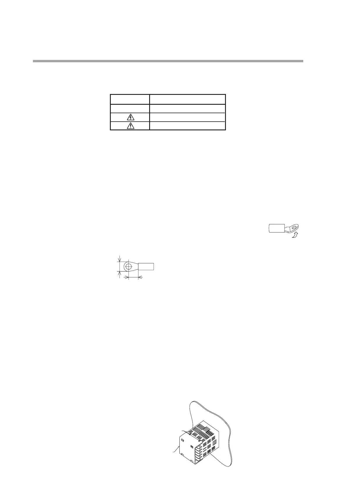
• For the C15T (panel-mount type), to connect 2 crimp terminals
to the same terminal screw, bend the crimp terminals before use.
• For the C15T (panel-mount type), connect wires to terminals 1-6 and 13-18 from
the left (when viewing the terminal block).
A: 5.8mm max. B: 5.5 to 7.6mm
Recommended crimp terminal: V1.25-MS3 (manufactured
by J.S.T. Mfg. Co., Ltd.)
• Keep the input/output signal cables 50cm or more away from the drive power
cable and/or power cable. Additionally, do not pass the input/output signal
cables and the drive power cable and/or power cable together through the same
conduit or duct.
• When connecting this unit and other measuring instrument in parallel, carefully
check the conditions necessary for other instrument before starting the
instrumentation.
• The digital input is so designed that it is non-voltage input. A contact for micro
current must be used.
• Pass the conductor, to which the heater current flows, through the current
transformer. Additionally, carefully check that the heater current does not
exceed the allowable current level stated in the specification. If the heater
current exceeds the allowable current level, this might cause damage to this unit.
• The input of the current transformer cannot be used for the phase angle control.
• For panel mounting type (C15T), an optional terminal cover is available to
prevent electric shock. (Model No.: 81446898-001)
Chapter 4. WIRING
Symbol Contents
~AC
Caution, Electric shock hazard
Caution