EasyManuals Logo

Azbil SDC15 User Manual

Azbil SDC15
146 pages
To Next Page IconTo Next Page
To Previous Page IconTo Previous Page
Page #35 background imageLoading...
Page #35 background image
4-3
The part between the control output 1 and control output 2 is not isolated. When
necessary, use an appropriate isolator.
Do not connect any terminating resistor to both ends of the RS-485
communication path. Doing so might cause the communication to fail.
Make sure that devices and equipment connected to this device have reinforced
insulation suitable for the maximum operating voltage of this device's power
supply and input/output ports.
This unit is so designed that it does not start functioning for up to 6 sec. after the
power has been turned ON to ensure stable operation. After 6 sec. have elapsed,
the unit enters the operation mode. However, to obtain the specified accuracy, it
is absolutely necessary to warm up the unit for 30 min. or longer.
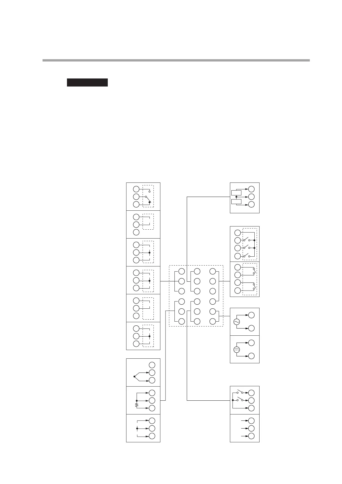
Wiring of C15T
Chapter 4. WIRING
1
2
3
13
14
15
1
2
1
2
3
1
2
3
1
2
3
1
2
4
5
6
13
14
15
16
17
18
7
8
9
10
11
12
1
2
3
4
5
6
4
5
6
4
5
6
Control output CT input
7
8
9
10
7
8
9
10
Event output
11
12
Power supply
Relay
Voltage pulse
Voltage pulse
Current
Current
Current
Current
Voltage
Voltage pulse
Voltage pulse
PV input
16
17
18
16
17
18
DI/COM
Thermocouple
RTD
Current
1
2
+
+
-
-
+
-
+
1
2
+
-
+
-
+
1
2
+
-
+
+
+
-
mA
V
CT1
CT2
Relay
Relay
independent
contact
100 to 240Vac
11
12
24Vac /
24 to 48Vdc
(non-polarity)
Digital input
RS-485
communication
DA
DB
SG
1
2
1
2
1
2
3
C
B
A
Important

Other manuals for Azbil SDC15

Questions and Answers:

Question and Answer IconNeed help?

Do you have a question about the Azbil SDC15 and is the answer not in the manual?

Azbil SDC15 Specifications

General IconGeneral
BrandAzbil
ModelSDC15
CategoryController
LanguageEnglish

Related product manuals