2
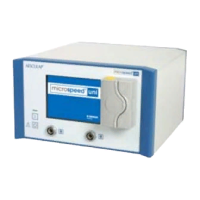
microspeed® uni motor system
Aesculap Power Systems
Legend
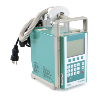
Captions first foldout page: Control unit
1 microspeed® uni control unit with cooling unit GD670
2 Display and touch control field
3 Release buttons
4 Coolant pump
5 Motor connection sockets
6 Power OFF switch
7 Power ON switch
8 Power ON indicator
9 Bottle holder
10 Bottle holder mount
11 Ventilation grate
12 Power socket
13 Fuse holder
14 Connection socket for foot control
15 Stacking cones
16 Locking screw
17 Equipotentialization connector
39 Interfaces to be used by the manufacturer only
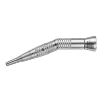
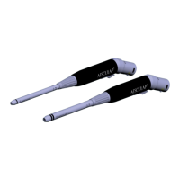
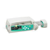
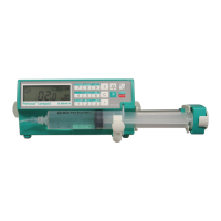
Captions second foldout page: Foot controls, motor cables, motors
18 Foot control function button
19 Right pedal
20 Left pedal
21 microspeed® uni foot control, two pedals, GD671
22 Motor direction switch
23 Pedal
24 microspeed® uni foot control, one pedal, GD668
25 Motor release switch
26 Hand control function button
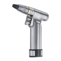
27 microspeed® uni motor cable with hand control GD673
28 Release key
29 Lever
30 Motor release switch
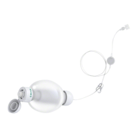
31 microspeed® uni motor cable for foot control GD672
32 Motors with motor-side plug connection
33 microspeed® uni mini pistol handpiece GD684
34 Upper trigger
35 Lower trigger
36 Suction control lever
37 microspeed® uni shaver handpiece GD682
38 Tube olive
Contents
1. Safe handling . . . . . . . . . . . . . . . . . . . . . . . . . . . . . . . . . . . . . . . . . 3
2. Product description . . . . . . . . . . . . . . . . . . . . . . . . . . . . . . . . . . . . 4
2.1 System components . . . . . . . . . . . . . . . . . . . . . . . . . . . . . . . . . . . . 4
2.2 Components necessary for using the product . . . . . . . . . . . . . . . 4
2.3 Intended use . . . . . . . . . . . . . . . . . . . . . . . . . . . . . . . . . . . . . . . . . . 4
2.4 Mode of operation . . . . . . . . . . . . . . . . . . . . . . . . . . . . . . . . . . . . . 4
2.4.1 Control unit. . . . . . . . . . . . . . . . . . . . . . . . . . . . . . . . . . . . . . . . . . . 4
2.4.2 Control and display interface . . . . . . . . . . . . . . . . . . . . . . . . . . . . 4
2.4.3 Control fields on the display . . . . . . . . . . . . . . . . . . . . . . . . . . . . . 5
2.4.4 Motor control fields . . . . . . . . . . . . . . . . . . . . . . . . . . . . . . . . . . . . 5
2.4.5 Pump control field . . . . . . . . . . . . . . . . . . . . . . . . . . . . . . . . . . . . . 6
2.4.6 Instruction menu . . . . . . . . . . . . . . . . . . . . . . . . . . . . . . . . . . . . . . 6
2.4.7 Motor recognition. . . . . . . . . . . . . . . . . . . . . . . . . . . . . . . . . . . . . . 6
2.4.8 Automatic saving of device settings . . . . . . . . . . . . . . . . . . . . . . . 6
2.4.9 Overload cut-out . . . . . . . . . . . . . . . . . . . . . . . . . . . . . . . . . . . . . . 7
2.4.10 Coolant pump . . . . . . . . . . . . . . . . . . . . . . . . . . . . . . . . . . . . . . . . . 7
2.4.11 Motor cable. . . . . . . . . . . . . . . . . . . . . . . . . . . . . . . . . . . . . . . . . . . 7
2.4.12 Motors . . . . . . . . . . . . . . . . . . . . . . . . . . . . . . . . . . . . . . . . . . . . . . . 9
2.4.13 Foot control devices . . . . . . . . . . . . . . . . . . . . . . . . . . . . . . . . . . . 11
2.5 Symbols . . . . . . . . . . . . . . . . . . . . . . . . . . . . . . . . . . . . . . . . . . . . . 12
2.5.1 Symbols on the control unit . . . . . . . . . . . . . . . . . . . . . . . . . . . . 12
2.5.2 Symbols on foot control, motor cable and motor . . . . . . . . . . . 12
2.5.3 Symbols in display . . . . . . . . . . . . . . . . . . . . . . . . . . . . . . . . . . . . 13
3. Preparation and setup . . . . . . . . . . . . . . . . . . . . . . . . . . . . . . . . . 15
3.1 Preparation . . . . . . . . . . . . . . . . . . . . . . . . . . . . . . . . . . . . . . . . . . 15
3.1.1 Mounting the control unit on the mobile stand . . . . . . . . . . . . 15
3.1.2 Dismounting the control unit from the mobile stand . . . . . . . . 15
3.1.3 Mains power connection . . . . . . . . . . . . . . . . . . . . . . . . . . . . . . . 15
4. Working with the microspeed® uni motor system. . . . . . . . . . . 16
4.1 System set-up . . . . . . . . . . . . . . . . . . . . . . . . . . . . . . . . . . . . . . . . 16
4.1.1 Connecting the accessories . . . . . . . . . . . . . . . . . . . . . . . . . . . . . 16
4.1.2 Connecting the foot control to the control unit . . . . . . . . . . . . 16
4.1.3 Connecting the tubing set . . . . . . . . . . . . . . . . . . . . . . . . . . . . . . 17
4.1.4 Connecting the motor cable to the control unit . . . . . . . . . . . . 17
4.1.5 Connecting a motor (GD674, GD676, GD677, GD678
and GD679) to the motor cable. . . . . . . . . . . . . . . . . . . . . . . . . . 18
4.1.6 Switching on the control unit/Automatic self-test . . . . . . . . . . 18
4.1.7 Connecting handpieces/attachments/blades . . . . . . . . . . . . . . . 18
4.2 Function checks . . . . . . . . . . . . . . . . . . . . . . . . . . . . . . . . . . . . . . 22
4.3 Safe operation. . . . . . . . . . . . . . . . . . . . . . . . . . . . . . . . . . . . . . . . 23
4.3.1 Setting up and operating the motors GD674, GD676,
GD677, GD678 and GD679 . . . . . . . . . . . . . . . . . . . . . . . . . . . . . 23
4.3.2 Setting up and operating
the microspeed® uni shaver handpiece GD682 . . . . . . . . . . . . . 26
4.3.3 Setting up and operating
the microspeed® uni mini pistol handpiece GD684. . . . . . . . . . 28
4.4 Settings in the Instruction menu . . . . . . . . . . . . . . . . . . . . . . . . 32
4.4.1 Submenu information on the error conditions
shown on the display . . . . . . . . . . . . . . . . . . . . . . . . . . . . . . . . . . 33
4.4.2 Submenu Device-specific settings . . . . . . . . . . . . . . . . . . . . . . . 33
4.4.3 Submenu Motor (type)-specific settings . . . . . . . . . . . . . . . . . . 35