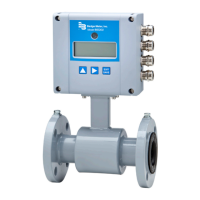
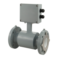
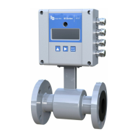
Technical data Page 35/44
MID_M2000_BA_02_1004
DN
A Std*
A
ISO**
B1
B2
ANSI flanges DIN flanges
D
K
d2xn ∅ D ∅ K
d2xn
6 1/4” 170 --- 228 288 88,9 60,3 15,9 x 4 90 60 14 x 4
8 3/10” 170 --- 228 288 88,9 60,3 15,9 x 4 90 60 14 x 4
10 3/8” 170 --- 228 288 88,9 60,3 15,9 x 4 90 60 14 x 4
15 1/2” 170 200 238 298 88,9 60,3 15,9 x 4 95 65 14 x 4
20 3/4” 170 200 238 298 98,4 69,8 15,9 x 4 105 75 14 x 4
25 1” 225 200 238 298 107,9 79,4 15,9 x 4 115 85 14 x 4
32 1 1/4” 225 200 253 313 117,5 88,9 15,9 x 4 140 100 18 x 4
40 1 1/2” 225 200 253 313 127 98,4 15,9 x 4 150 110 18 x 4
50 2” 225 200 253 313 152,4 120,6 19 x 4 165 125 18 x 4
65 2 1/2” 280 200 271 331 177,8 139,7 19 x 4 185 145 18 x 4
80 3” 280 200 271 331 190,5 152,4 19 x 4 200 160 18 x 8
100 4” 280 250 278 338 228,6 190,5 19 x 8 220 180 18 x 8
125 5” 400 250 298 358 254 215,9 22,2 x 8 250 210 18 x 8
150 6” 400 300 310 370 279,4 241,3 22,2 x 8 285 240 22 x 8
200 8” 400 350 338 398 342,9 298,4 22,2 x 8 340 295 22 x 12
250 10” 500 450 362 422 406,4 361,9 25,4 x 12 395 350 22 x 12
300 12” 500 500 425 485 482,6 431,8 25,4 x 12 445 400 22 x 12
350 14” 500 550 450 510 533,4 476,2 28,6 x 12 505 460 22 x 16
400 16” 600 600 475 535 596,9 539,7 28,6 x 16 565 515 26 x 16
450 18” 600 --- 500 560 635,0 577,8 31,7 x 16 615 565 26 x 20
500 20” 600 --- 525 585 698,5 635,0 31,7 x 20 670 620 26 x 20
550 22” 600 --- 550 610 749,3 692,1 34,9 x 20 --- --- ---
600 24” 600 --- 588 648 812,8 749,3 34,9 x 20 780 725 30 x 20
650 26” 600 --- 613 673 869,9 806,4 34,9 x 24 --- --- ---
700 28” 600 --- 625 685 927,1 863,6 35,1 x 28 895 840 30 x 24
750 30” 800 --- 650 710 984,2 914,4 34,9 x 28 --- --- ---
800 32” 800 --- 683 743 1060,5 977,9 41,3 x 28 1015 950 33 x 24
850 34” 800 --- 708 768 1111,2 1028,7 41,3 x 32 --- --- ---
900 36” 800 --- 725 785 1168,4 1085,8 41,3 x 32 1115 1050 33 x 28
950 38” 800 --- 750 810 1238,3 1149,4 41,3 x 32 --- --- ---
1000 40” 800 --- 790 850 1346,2 1257,3 41,3 x 36 1230 1160 36 x 28
1200 48” 1000 --- 900 960 1511,5 1422,4 41,3 x 44 1455 1380 39 x 32
1350 54” 1000 --- 975 1035 1682,8 1593,9 47,8 x 44 --- --- ---
1400 56” 1000 --- 1000 1060 --- --- --- 1675 1590 42 x 36
Standard
ANSI flanges from DN 6 - 2000 pressure 150 lbs
DIN flanges from DN 6 – 200 pressure PN 16
from DN 250 – 2000 pressure PN 10
* Standard **ISO 13359
 Loading...
