64394-032 Wall Cover Install Kit
ORI-UM-00025-EN-19
• If the endpoint has an in-line connector, place the connector inside with the
endpoint and route the connector cable through the cutout on the bottom.
OTE:N If used, place gel splice connections inside the enclosure.
OTE:N See "Outdoor Installation for Endpoint with In-line Connector" on
page 16 for additional information about installing the endpoint
outdoors with the wall cover enclosure.
5. Make sure the wall cover is properly positioned, with the endpoint antenna
straight up and the endpoint IR LED port visible through the bottom opening.
6. Secure the wall cover using customer-supplied screws.
Installation is complete.
Figure 11: 64394-032 installation complete
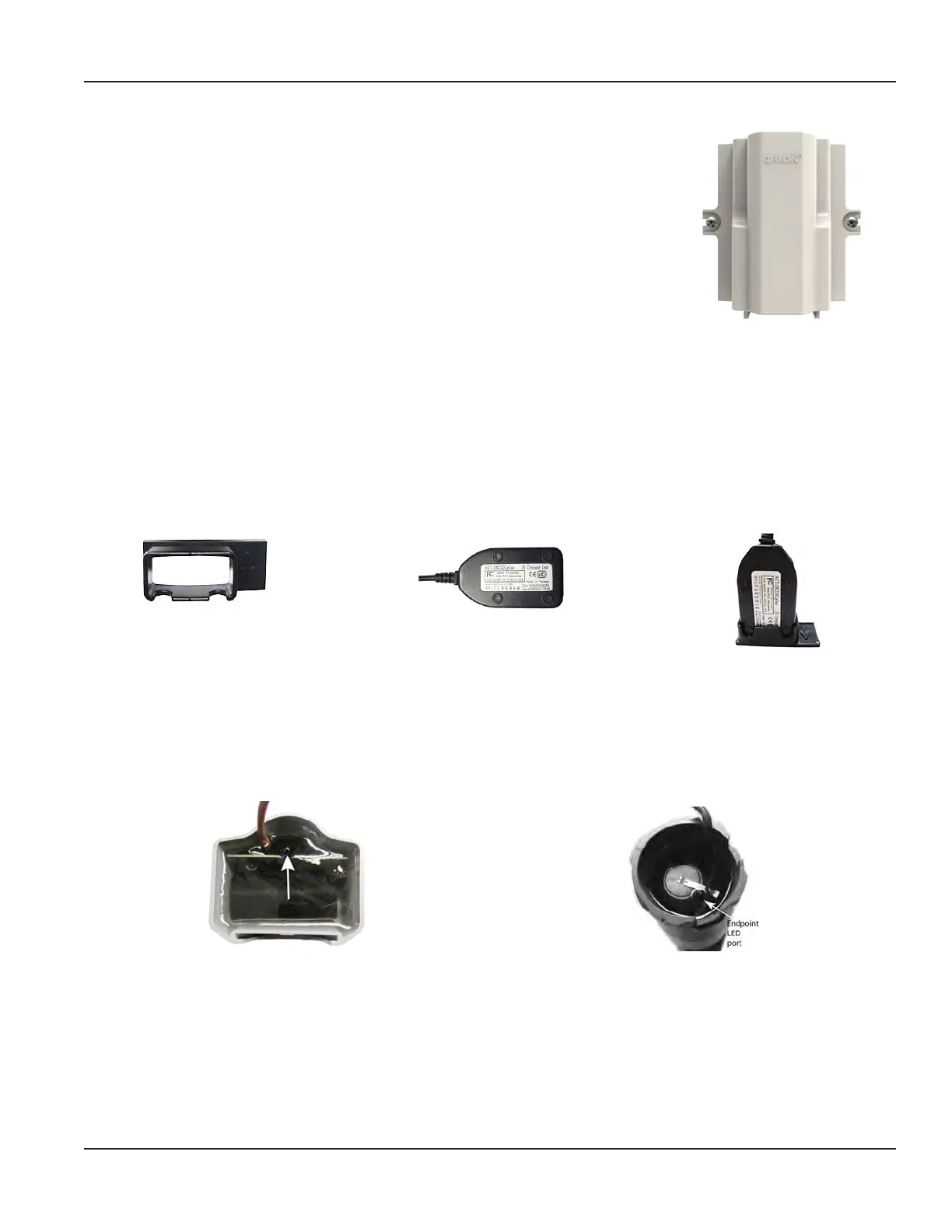
67625-001 IR Holder for Wall Cover Install Kit
IR Holder for Wall Cover Install Kit (PN: 67625-001) is an optional part which can be ordered for use with the Wall Cover
install kit (64394-032). The IR holder bracket fits on the wall cover adapter rails to hold an IR programming head in place.
1. Place the optical head of an IR programming cable into the holder. The nubs on the optical head t into the cutouts
on the holder.
(PN: 67625-001) IR holder bracket
Optical head of the IR programming cable
Optical head in the bracket
Figure 12: IR holder and programming cable optical head
2. Slide the bracket into the adapter rails at the bottom of the wall cover enclosure (64394-032) so the IR optical head
is aligned with the endpoint LED port. See Figure 13 and Figure 14.
3. Connect the IR programming cable to a Badger Meter mobile reading device to perform IR functions. Refer to the
mobile reading device user manual for IR programming instructions.
Figure 13: IR LED port ORION Cellular LTE endpoint (bottom up view)
Figure 14: IR LED port ORION ME endpoint (bottom up view)
Page 15 February 2019

 Loading...


