Using Gel Caps to Connect an Encoder
ORI-UM-00025-EN-19
USING GEL CAPS TO CONNECT AN ENCODER
For those connections that are not factory wired or equipped with in-line connectors, follow these guidelines for using gel
caps when splicing is required, either for installation or to fix a connection after a tamper. Refer to the wiring charts for each
ORION endpoint, starting on page 6.
OTE:N
• For pit environments, splice connections require a field splice kit (PN: 62084-001), which can be ordered separately.
Refer to Field Splice Kit for Badger Meter AMR/AMI Products, available in the Resource Library at www.badgermeter.com.
• For all installations, excess wire should be coiled and cable tied to avoid any damage.
Required Tools
Splicing Tools (Customer Supplied) Badger Meter Part Number
• Parallel Pliers 59983-001
• Coax Wire Stripper 59989-001
• Diagonal Cutting Pliers n/a
Connecting an Encoder Using Gel Caps
Follow these steps when using Badger Meter supplied gel caps.
1. To connect an encoder with existing wires to an ORION endpoint, strip approximately 1-1/2 inches (38 mm) of outer
insulation sheath from the encoder and endpoint cables using a coax wire stripping tool. We recommend using the
Badger Meter Coax Wire Stripper (PN: 59989-001).
USE CAUTION WHEN REMOVING THE OUTER SHEATH SO THAT THE INNER SIGNAL WIRE INSULATION IS NOT
NICKED OR DAMAGED.
2. Unwind the outer foil shield from the endpoint cable and cut it o even with the outer sheath using diagonal
cutting pliers.
3. Connect the ORION endpoint to an approved encoder. Verify the endpoint serial number prior to completing the
wiring setup.
• Connect the encoder cable wires to the ORION endpoint wires using the insulation gel caps provided in the
installation kit. Refer to the wiring charts for the endpoint type starting on page 6 and determine which wires
need to be connected to complete an installation.
OTE:N The terminal posts and wire colors may not match.
DO NOT STRIP ANY INSULATION FROM THE ENDS OF THE WIRES BEFORE YOU PUSH THEM INTO THE
GEL CAP.
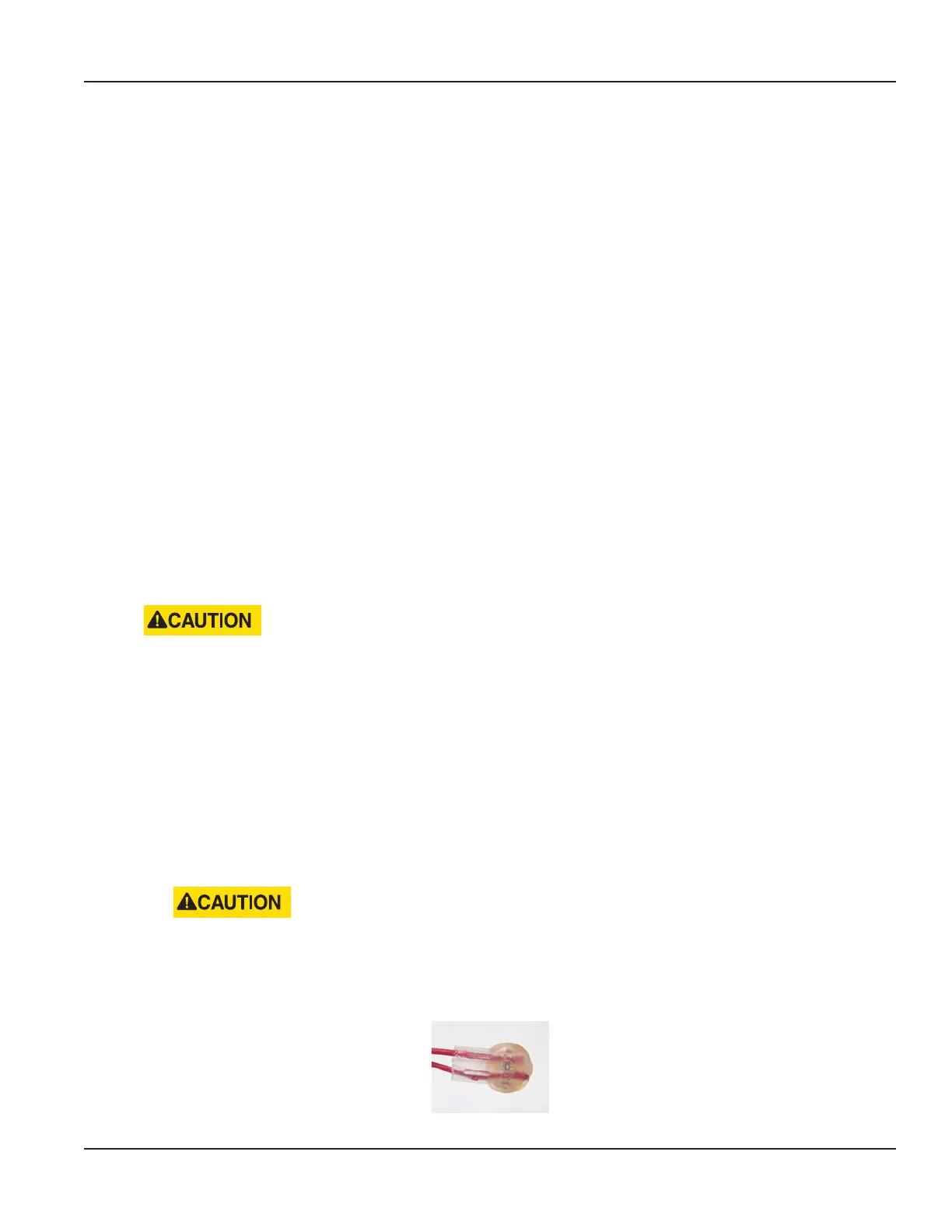
• Insert the wires from each cable end as far as possible into the gel cap. See Figure 58: Wires in gel cap.
Figure 58: Wires in gel cap
Page 31 February 2019
 Loading...


