MODULAR POWER SYSTEM SIZING TABLES
INTRODUCTION
I-E96-508C D - 3
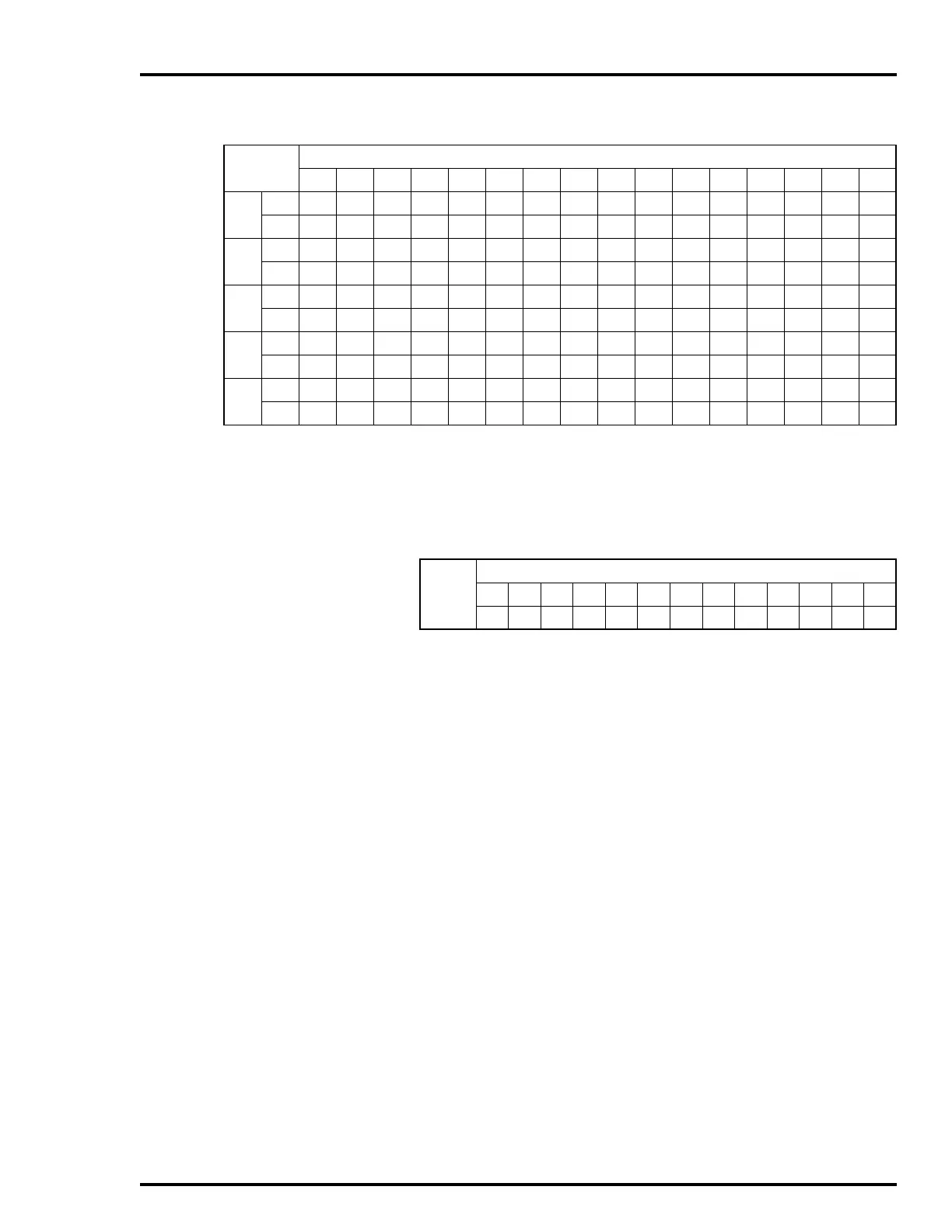
Use Table D-3 to determine the value of Q2 using C (the +15
VDC current requirements for the cabinet) and Q3 using D (the
-15 VDC current requirements for the cabinet).
80 Q1
8888888888888888
QF
0000000001234567
85 Q1
9999999999999999
QF
0000000000123456
90 Q1
9999999999999999
QF
0000000000123456
95 Q1
10 10 10 10 10 10 10 10 10 10 10 10 10 10 10 10
QF
0000000000012345
100 Q1
10 10 10 10 10 10 10 10 10 10 10 10 10 10 10 10
QF
0000000000012345
Table D-2. Q1 and QF for Systems Using IEPDS01/02 and IEPDF01/02 Modules
(continued)
A
B
024681012141618202224262830
Table D-3. Q2 or Q3 for All Power Systems
Q2 or
Q3
C or D
00.511.522.533.544.555.56
0123456789101112