INSTALLATION
SETUP/PHYSICAL INSTALLATION
I-E96-409A 2 - 7
6634408_2 RIBBON CABLE
This cable connects the ICS module to an NIDS01 module. To
install the cable:
1. Insert one end of the cable into the J1 connector of the ICS
module.
2. Insert the other end of the cable into the J1 connector of
the NIDS01 Termination Module.
Installing the Termination Module
The ICS module inserts into a standard INFI 90 termination
mounting unit (TMU) and occupies one slot. To install:
NOTE:
Insure all dipswitches are configured prior to installation.
1. Verify slot assignment of the ICS module.
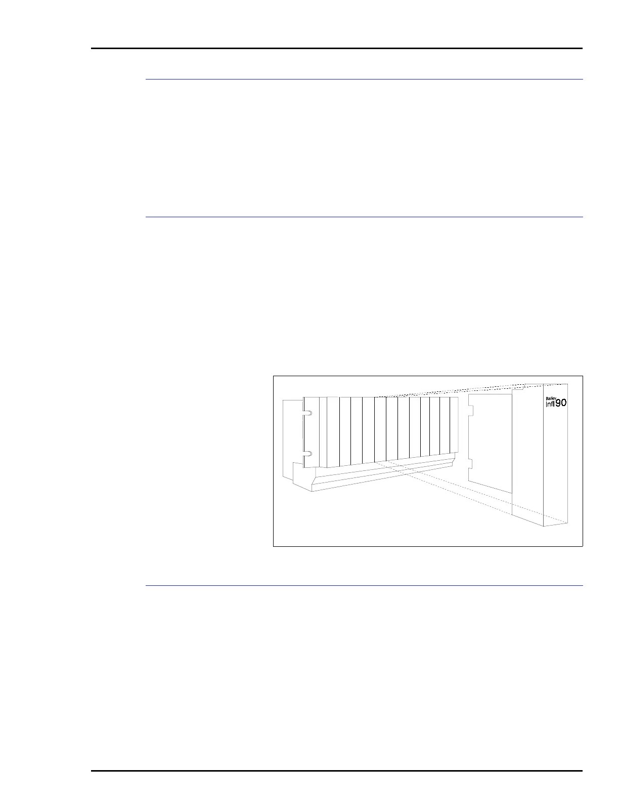
2. Align the ICS module with the guide rails in the termina-
tion mounting unit and partially insert the module (See
Figure 2-5).
Terminal Wiring
Field, serial link and power wiring must be connected to the
terminal strip. See Figure 2-6 for ICS terminal strip assign-
ments. The serial link provides a communication path between
a master module and stations. Serial link wiring should be
Bailey serial link wire. See Figure 2-7 for example input
circuits.
Figure 2-5. Termination Module Installation
1
6
2
3
4
5
7
8
9
10
11
12
T00501A