INTRODUCTION
I-E96-409A E - 1
APPENDIX E - IISAC01 ANALOG CONTROL
STATION CONFIGURATION
INTRODUCTION
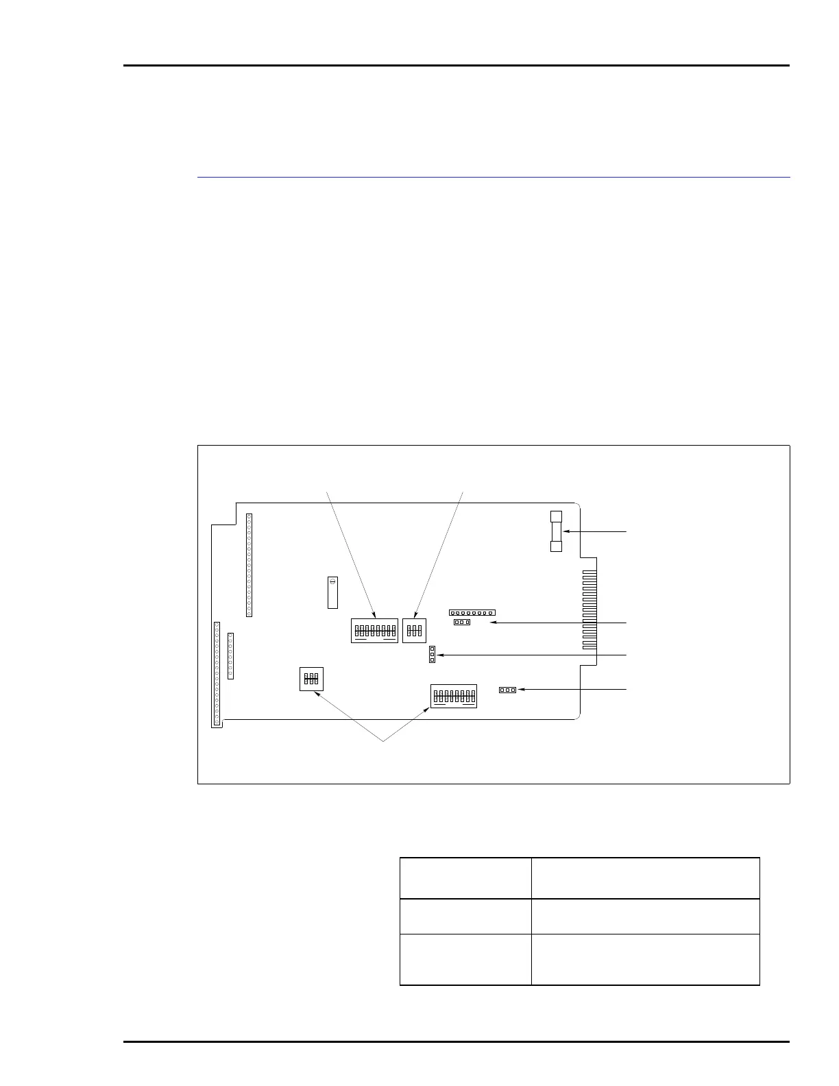
Figure E-1 shows the location of the dipswitches and jumpers
used to configure the SAC station. Tables E-1, E-2, E-3, E-4,
and E-5 give the dipswitch and jumper settings to configure
the station. This information is provided as a quick reference
guide for personnel installing the NICS01 module. Configura-
tion consists of setting the operating mode, communications
rate and station address (Switch S1). The auto bypass, output
and electric drive options (Switch S2) along with the bar graph
display option (Switches S3 and S4) must be set. Jumpers J1
through J3 set the manual override, electric drive type and
normal operation options. Refer to the Analog Control Sta-
tion (IISAC01) instruction manual for detailed
instructions.
Figure E-1. Analog Control Station
P3
P6
P2
S3
S4
JP1
JP2
JP3
P5
F1
P1
S1
R130
S2
T00504A
123
123
1
2
3
12
OPEN
3
12
OPEN
3
OPEN
12345678
OPEN
12345678
OPERATING MODE,
COMMUNICATION RATE AND
MODULE ADDRESS SWITCH
AUTO BYPASS, OUTPUT
AND ELECTRIC DRIVE
OPTION SWITCH
1-AMP FUSE
MANUAL OVERRIDE OPTION
JUMPER
NORMAL OPERATION
OPTION JUMPER
ELECTRIC DRIVE TYPE
OPTION JUMPER
BAR GRAPH DISPLAY
OPTION SWITCHES
Table E-1. Switch S1 Settings
Switch Positions
Function
12
1
0
Diagnostics mode.
Normal mode.
1
0
Enables 40 kbaud communication rate
(IMMFP01/02/03).
Enables 5 kbaud communication rate.