IISAC01 ANALOG CONTROL STATION CONFIGURATION
INTRODUCTION
I-E96-409A E - 3
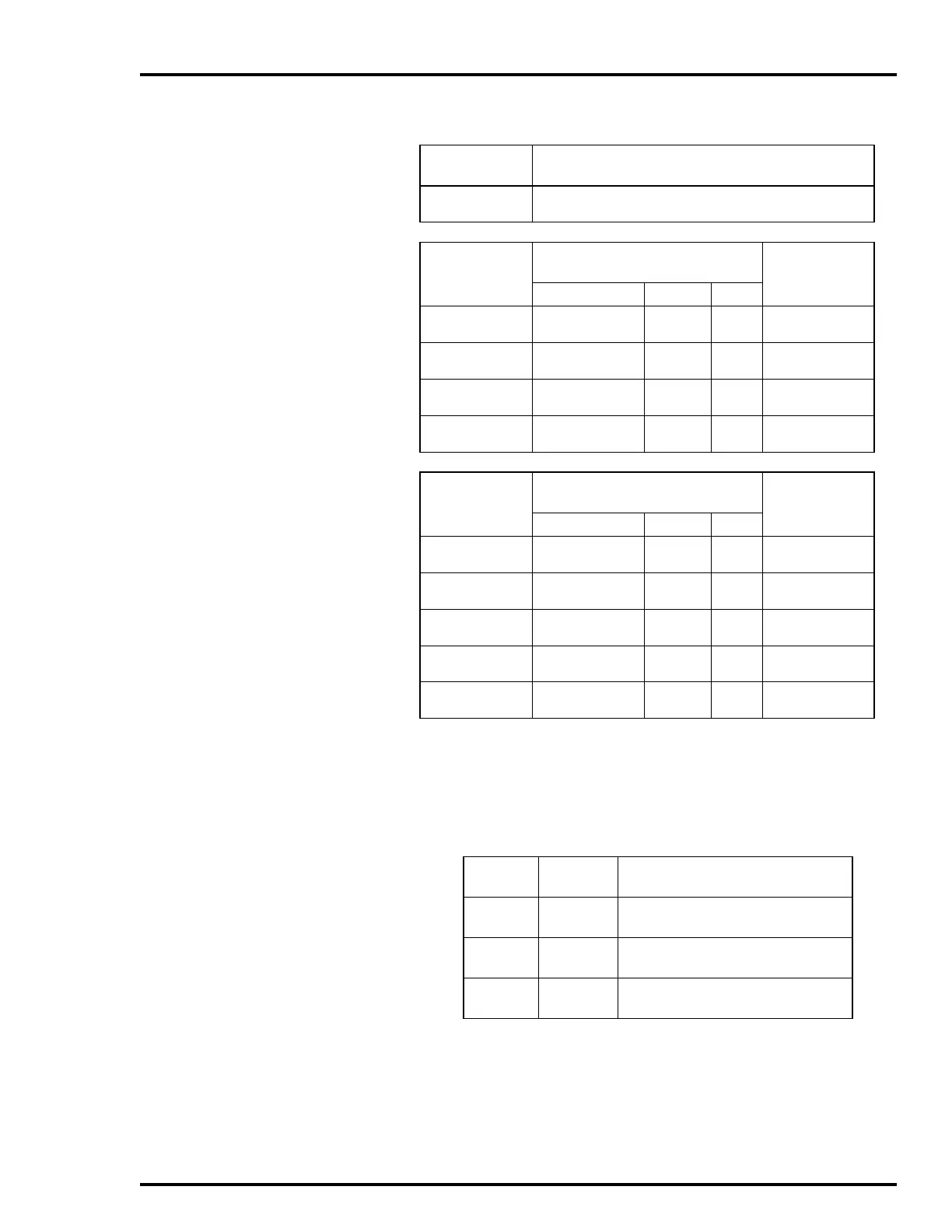
Table E-4. Switch S4 Settings
Switch
Position
Function
1
0
Enables square root of AI2.
Disables square root of AI2.
Switch
Position
234
Bar Graph Display Options
(Normal Mode)
Alphanumeric
Display
VAR OUT SET
000
001
PV
PV
CO
AI1
SP
SP
PV, CO, SP
PV, CO, SP
010
011
PV
PV
Blank
All On
SP
SP
PV, CO, SP
PV, CO, SP
100
101
AI2
AI2
CO
AI1
SP
SP
PV, CO, SP
PV, CO, SP
110
111
AI2
AI2
Blank
All On
SP
SP
PV, CO, SP
PV, CO, SP
Switch
Position
5678
Bar Graph Display Options
(Bypass Mode)
Alphanumeric
Display
VAR OUT SET
0000
1
0001
Blank
Blank
AI1
DO
N/A
N/A
DO
2
DO
0010
0011
AI1
DO
DO
DO
N/A
N/A
DO
DO
0100
0101
1
DO
AI2
AI1
AI1
N/A
N/A
DO
DO
2
0110
0111
AI2
PV(MFP)
DO
AI1
N/A
N/A
DO
PV, DO
1000
1001
1
PV(MFP)
Blank
DO
Blank
N/A
N/A
PV, DO
DO
2
NOTES:
0 represents the CLOSED or ON side of the switch. 1 represents the OPEN or OFF
side of the switch.
AI = Analog Input, CO = Control Output, DO = Demand Output, PV = Process Variable, SP =
Set Point.
1. The only display options available when electric drive is enabled.
2. Alphanumeric display is blanked when electric drive is enabled.
Table E-5. Jumper JP1, JP2, and JP3 Settings
Jumper
Jumper
Position
Function
JP1 1-2
2-3
Enable manual override switch.
Disable manual override switch.
JP2
1
1-2
2-3
RW type electric drive.
Universal type electric drive.
JP3 1-2
2-3
Normal operation.
Factory setting
2
.
NOTES:
1. This jumper is labeled JP4 on stations that are revision 6638095A1.
2. This setting used during factory testing.
Do not
use this setting during normal
operation.