INTRODUCTION
I-E96-409A G - 5
APPENDIX G - NDIS01 DIGITAL INDICATOR
STATION CONFIGURATION
INTRODUCTION
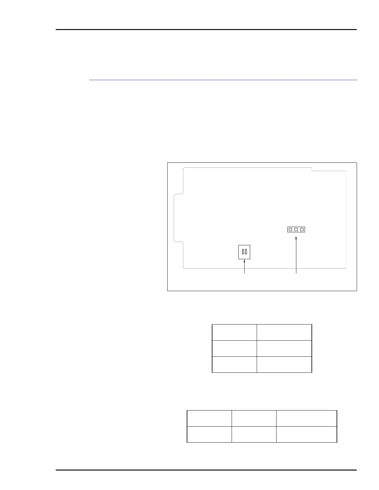
Figure G-1 shows the location of the dipswitches and jumpers
used to configure the DIS station. Tables G-1 and G-2 give the
dipswitch and jumper settings to configure the station. This
information is provided as a quick reference guide for person-
nel installing the NICS01 module. Configuration consists of
setting the station address (Switch S1) and display brightness
(Jumper JP1). Refer to the Digital Indicator Station
(NDIS01) instruction manual for detailed instructions.
Figure G-1. Digital Indicator Station
Table G-1. Address Switch Settings
Station
Address
Switch Position
12
8
9
00
01
10
11
10
11
NOTE: 0 represents the CLOSED or ON side of
the switch. 1 represents the OPEN or OFF side of
the switch.
Table G-2. Jumper J1 Settings
Jumper
Jumper
Position
Function
JP1 1-2
2-3
Select bright intensity.
Select dim intensity.
JP1
213
OPEN
12
S1
ADDRESS SWITCH DISPLAY BRIGHTNESS
JUMPER
T00476A