IISAC01 ANALOG CONTROL STATION CONFIGURATION
INTRODUCTION
E - 4 I-E96-409A
®
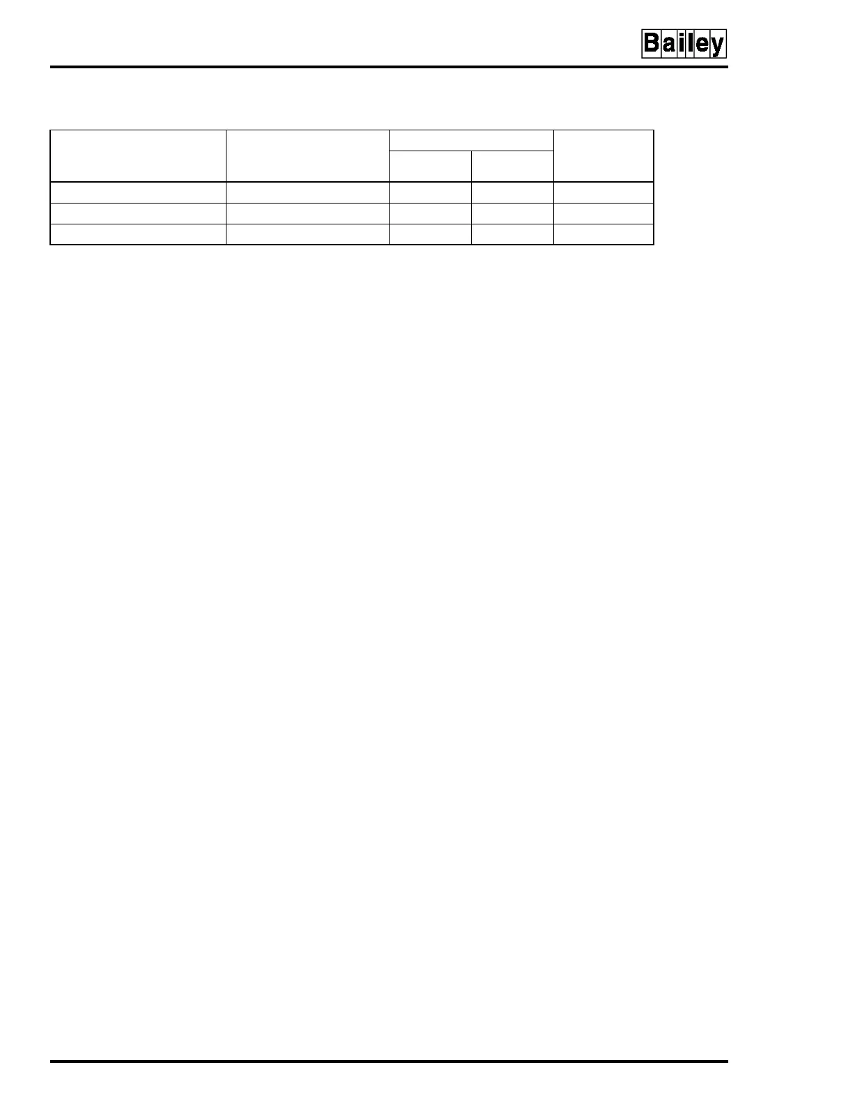
Table E-6. Electric Drive Mode Display Options
Standalone Display Mode
(Switch S3 Positions)
123
Bypass Display Mode
(Switch S4 Positions)
5678
Bar Graph
Action on
Control Output
VAR OUT
0 0 1 0 0 0 0 Blank AI1 AI1 to CO
1 1 0 0 1 0 1 AI2 AI1 AI1 to CO
1 1 1 1 0 0 1 AI2 AI1 AI2 to CO
NOTE:
0 represents the CLOSED or ON side of the switch. 1 represents the OPEN or OFF side of the switch. AI = Analog Input, CO =
Control Output.