IMQRC01 QUICK RESPONSE CONTROLLER MODULE CONFIGURATION
INTRODUCTION
C - 2 I-E96-409A
®
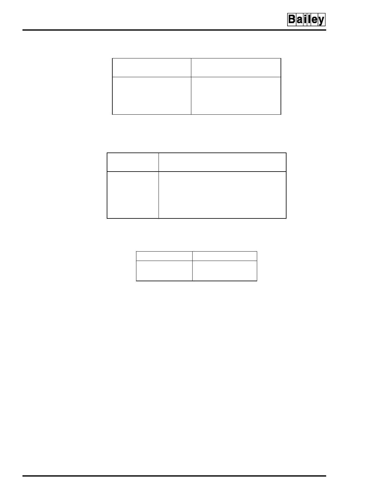
Table C-2. Switch S4 Settings (Modes)
Function
Switch Position
12345678
Normal mode:
Normal operation 00000000
NVRAM initialization 01000000
Configuration lockout 00100000
NOTE:
0 represents the CLOSED or ON side
of the switch. 1 represents the OPEN or OFF
side of the switch.
Table C-3. Switch S4 Settings (Module Address)
Address Example
Switch Position 4 5 6 7 8
Binary Value 16 8 4 2 1
0 00000
8 01000
16 10000
24 11000
31 11111
NOTE:
0 represents the CLOSED or ON side of the switch.
1 represents the OPEN or OFF side of the switch.
Table C-4. Jumper J1, J2 and J3 Settings
Jumper Position Digital Input Type
1-2
2-3
24 VDC
125VDC