IMCIS02 CONTROL I/O SLAVE MODULE CONFIGURATION
INTRODUCTION
A - 2 I-E96-409A
®
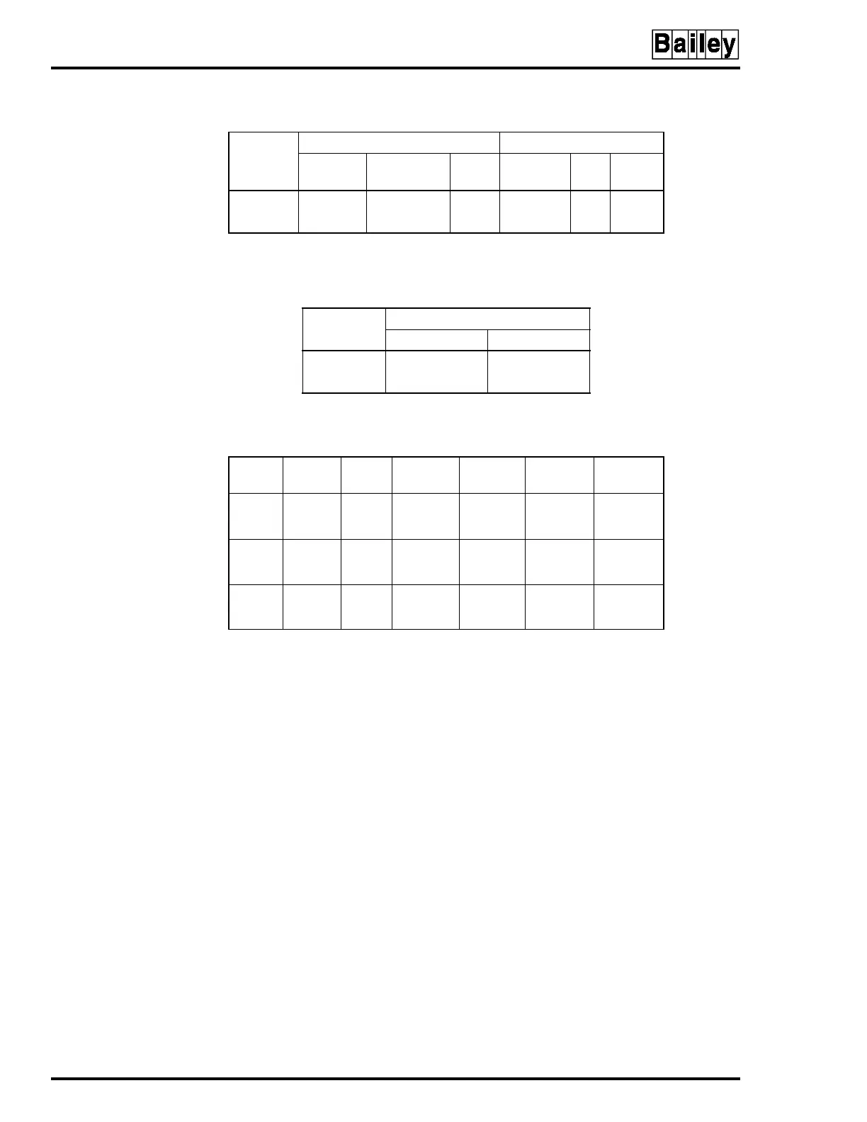
Table A-2. Switch S2 Settings
Analog
Output
Time-out Option Power Up State
Switch
Go To
Power Up
Hold Switch 0% 100%
12 01301
25 01601
NOTE:
0 represents the CLOSED or ON side of the switch. 1 represents the OPEN or OFF side of
the switch. Switch Positions 1 and 4 are not used and must be set to 0 or CLOSED state.
Table A-3. Switch S3 Settings
Analog
Output
Switch Position
Current Mode Voltage Mode
1C1 C2
2C3 C4
NOTE:
Current Mode = 4 to 20 mA, Voltage Mode = 1 to 5 VDC+
Table A-4. Jumpers J1 through J6 Settings
Digital
Input
Jumper
120
VAC
125 VDC
Slow
125 VDC
Fast
24 VDC
Slow
24 VDC
Fast
11
4
1-2
1-2
2-3
2-3
2-3
3-4
3-4
2-3
3-4
3-4
22
5
1-2
1-2
2-3
2-3
2-3
3-4
3-4
2-3
3-4
3-4
33
6
1-2
1-2
2-3
2-3
2-3
3-4
3-4
2-3
3-4
3-4
NOTE:
Slow = 17 millisecond response time, Fast = 1.5 millisecond response time.
Do not
remove
Jumper 7 or the module will operate erratically.