INTRODUCTION
I-E96-409A F - 1
APPENDIX F - NDCS03 DIGITAL CONTROL
STATION CONFIGURATION
INTRODUCTION
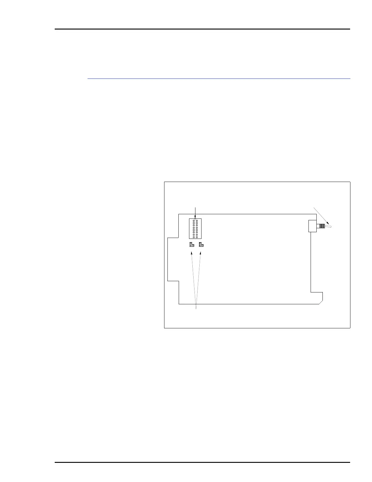
Figures F-1 and F-2 show the location of the dipshunts,
dipswitches and jumpers used to configure the DCS station.
Tables F-1, F-2, F-3, and F-4 give the dipswitch, dipshunt and
jumper settings to configure the station. This information is
provided as a quick reference guide for personnel installing the
NICS01 module. Configuration consists of setting the analog
input type (Dipshunt XU16) and control output type (Jumpers
J1 and J2) on the bypass board. Setting the station address
(Switch S1) and options (Jumpers JP1 through JP5) on the sta-
tion board is also required. Refer to the Digital Control Sta-
tion (NDCS03) instruction manual for detailed instructions.
Figure F-1. Bypass Board
1
116
215
710
611
512
413
314
89
1
CONTROL OUTPUT
JUMPERS
T00505A
J1 J2
XU16
22
33
ANALOG INPUT
TYPE DIPSHUNT
MANUAL BYPASS SWITCH:
UP = BYPASS OPERATION
DOWN = OPERATION
NORMAL (NOT BYPASS)