INTRODUCTION
I-E96-409A C - 1
APPENDIX C - IMQRC01 QUICK RESPONSE CONTROLLER
MODULE CONFIGURATION
INTRODUCTION
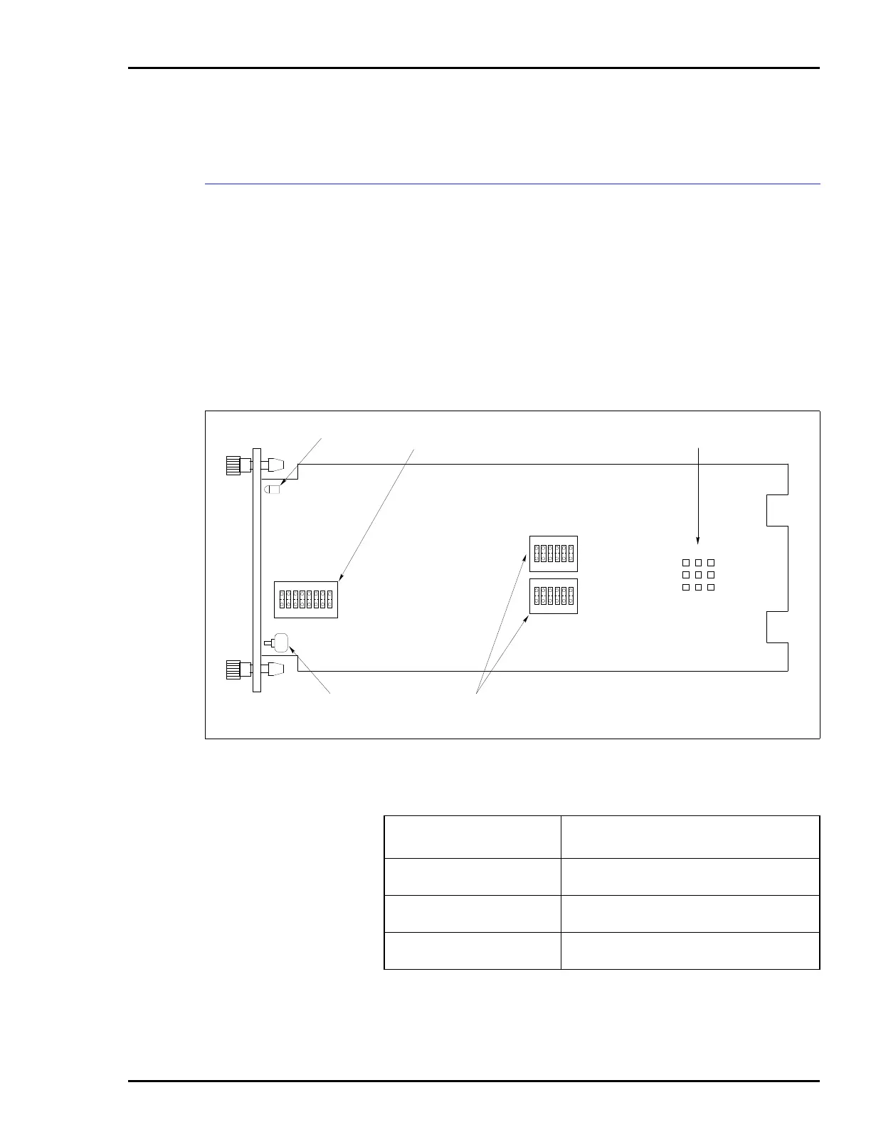
Figure C-1 shows the location of the dipswitches and jumpers
used to configure the QRC module. Tables C-1, C-2, C-3, and
C-4 give the dipswitch and jumper settings to configure the
module. This information is provided as a quick reference
guide for personnel installing the NICS01 module. Configura-
tion consists of setting the analog output types and defaults
(Switches S2 and S3), operating mode and module address
(Switch S4), and digital input types (Jumpers J1 through J3).
Refer to the Quick Response Controller (IMQRC01) instruc-
tion manual for detailed instructions.
Figure C-1. Quick Response Controller Module
T00030B
P1
P2
P3
STATUS LED ADDRESS/
TEST SWITCH
DIGITAL INPUT
TYPE JUMPER
MODULE RESET
SWITCH
ANALOG OUTPUT
SWITCHES
S4
S3
S2
1234
OPEN
5678
OPEN
OPEN
123456
123456
J1
J3
J2
123
Table C-1. Switch S2 and S3 Settings
Switch Positions
Function
123456
1
0
5.25 VDC analog output during power up.
0.75 VDC analog output during power up.
1
0
0
1
Holds last analog output value on time-out.
Goes to power up value on time-out.
0
1
1
0
0
1
Yields voltage output (1 to 5 VDC).
Yields current output (4 to 20 mADC).
NOTE: 0 represents the CLOSED or ON side of the switch. 1 represents the OPEN or OFF side of
the switch.