INTRODUCTION
I-E96-409A A - 1
APPENDIX A - IMCIS02 CONTROL I/O SLAVE
MODULE CONFIGURATION
INTRODUCTION
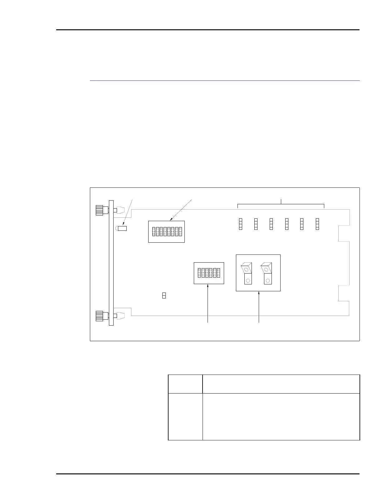
Figure A-1 shows the location of the dipswitches and jumpers
used to configure the CIS module. Tables A-1, A-2, A-3, and
A-4 give the dipswitch and jumper settings to configure the
module. This information is provided as a quick reference
guide for personnel installing the NICS01 module. Configura-
tion consists of setting the slave module address (Switch S1),
analog output default values (Switch S2), analog output mode
(Switch S3), digital input voltage level (Jumpers J1 through
J3), and DC voltage response time (Jumpers J4 through J6).
Refer to the Control I/O Slave Module (IMCIS02) instruction
manual for detailed instructions.
Figure A-1. Control I/O Slave Module
DIGITAL INPUT TYPE JUMPERS
ANALOG OUTPUT
MODE SWITCH
ANALOG OUTPUT
DEFAULT SWITCH
P1
P3
P2
ADDRESS SWITCH
J7
S1
MODULE STATUS LED
18
OPEN
S2
16
OPEN
2
1
T00503A
4
1
J6
4
1
J3
4
1
J5
4
1
J2
4
1
J4
4
1
J1
C1
C2
C3
C4
S3
Table A-1. Example Switch S1 Settings
Address
Example
Switch Position12345678
Binary Value1286432168421
0 00000000
16 00010000
32 00100000
48 00110000
63 01111111
NOTE: 0 represents the CLOSED or ON side of the switch. 1 represents the OPEN or OFF side of
the switch. Switch positions 1 and 2 must remain closed.