35
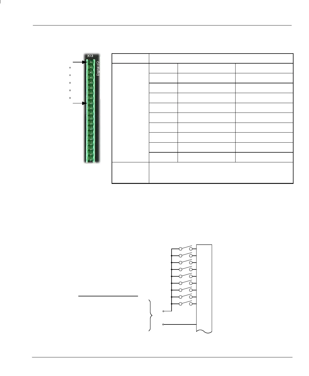
3.3.1 Digital Inputs - X13
Location Connector X13
Pin Name Mint keyword
1 Drive Enable -
2 DIN10 IN.10
3 DIN11 IN.11
4 DIN12 IN.12
5 DIN13 IN.13
6 DIN14 IN.14
7 DIN15 IN.15
8 DIN16 IN.16
9 DIN17 IN.17
Description Eight general purpose optically isolated AC digital inputs
(DIN10 to DIN17).
One committed drive enable input (Drive Enable).
The digital inputs DIN10 - DIN17 can be read individually using the associated Mint IN keyword (for
example IN.10) and can be configured for any number of user definable functions. These inputs are
sampled every 15.36ms. If a faster response is required, DIN0~DIN9 on connector X5 can be used.
Each of the AC optically isolated digital inputs has one side connected internally via a current limiting
resistor to the signal on pin 12, CREF. The other side appears as a separate pin on connector X13, for
use by the end user.
Enable
X13
1
A
B
DIN10 (IN.10)
2
DIN11 (IN.11)
3
DIN12 (IN.12)
4
DIN13 (IN.13)
5
DIN14 (IN.14)
6
DIN15 (IN.15)
7
DIN16 (IN.16)
8
DIN17 (IN.17)
9
(not connected)
10
(not connected)
11
CREF
12
External +24VDC supply
Active high: A=+24VDC
B=0V
Active low: A=0V
B=+24VDC
Figure 15 - X13 Digital inputs
1
9