12 english
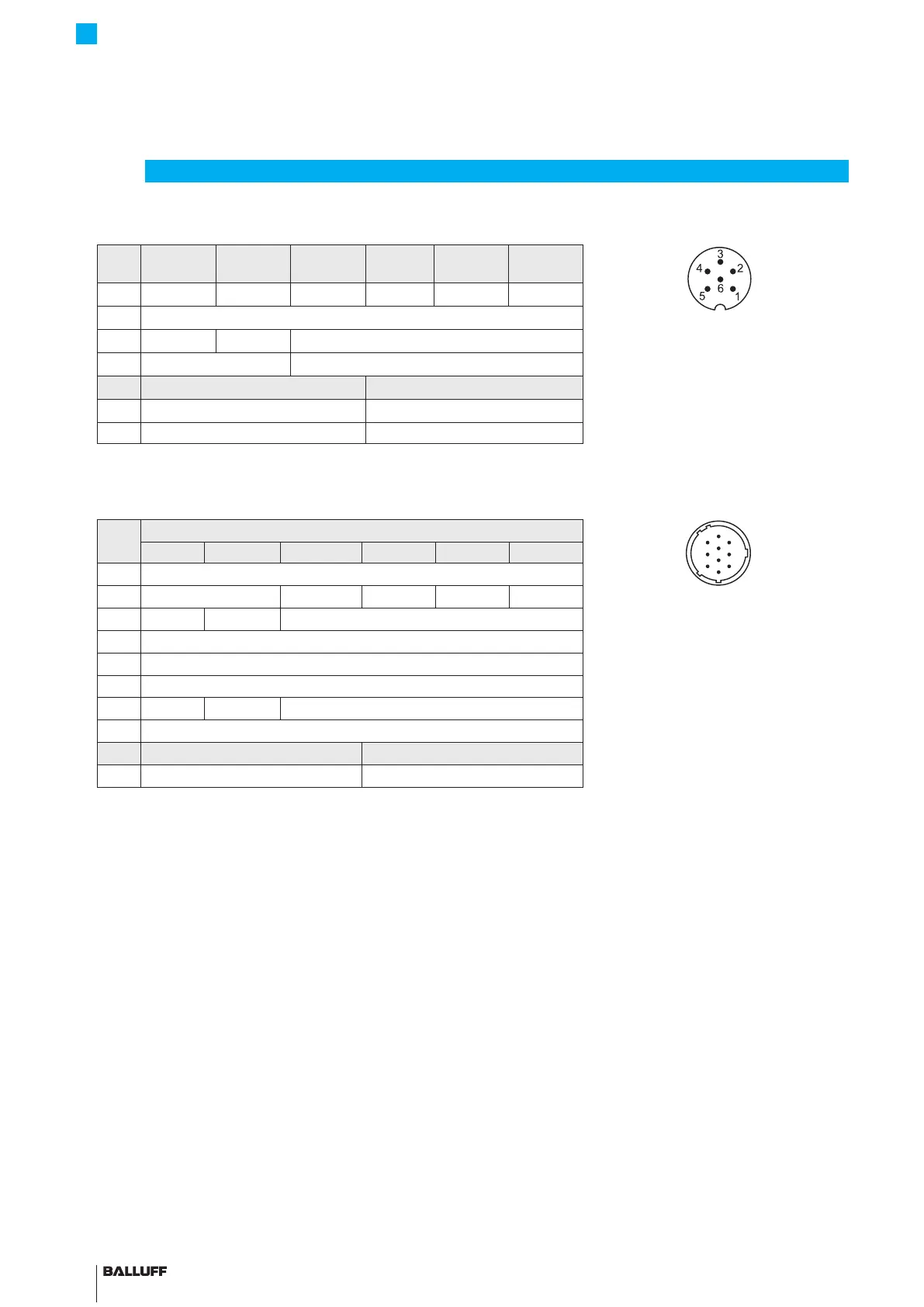
4.4.3 Connector type S135
S135
Pin
-A_10 -G_10 -C_00 -C_70 -E_00 -E_70
Fig. 4-11: Pin assignment of S135 (view of
connector pins of transducer), 6-pin
M16 circular plug
1)
Unassigned leads can be connected to the GND
on the controller side but not to the shield.
2)
Reference potential for supply voltage and
EMC-GND.
1 0 to 10V -10 to 10V 0 to 20 mA 20 to 0 mA 4 to 20 mA 20 to 4 mA
2 0 V (pin 1)
3 10 to 0V 10 to -10V Not used
1)
4 0 V (pin 3) Not used
1)
BTL7-_1_ _-... BTL7-_5_ _-...
5 20 to 28V 10 to 30V
6 GND
2)
GND
2)
Tab. 4-4: Connection assignment BTL7...-S135
4.4.4 Connector type S140
S140
Pin
Interface BTL7-...
A
B
C
J
K
G
H
E
D
F
Fig. 4-12: Pin assignment of S140 (view of
connector pins of transducer), 10-pin
circular plug
1)
Unassigned leads can be connected to the GND
on the controller side but not to the shield.
2)
Reference potential for supply voltage and
EMC-GND.
-A_10 -G_10 -C_00 -C_70 -E_00 -E_70
A 0 V
B Not used
1)
0 to 20mA 20 to 0mA 4 to 20mA 20 to 4mA
C 10 to 0V 10 to –10V Not used
1)
F GND
2)
G La (programming input)
H Lb (programming input)
J 0 to 10V –10 to 10V Not used
1)
K / E Not used
1)
BTL7-_1_ _-... BTL7-_5_ _-...
D 20 to 28V 10 to 30V
Tab. 4-5: Connection assignment BTL7...-S140
4
Installation and connection (continued)
BTL7-A/C/E/G_ _ _-M_ _ _ _-A/B/Y/Z(8)-S32/S115/S135/S140/KA_ _/FA_ _
Micropulse Transducer - Rod Style
 Loading...


